Manufacturing equipment for upper-and-lower intercalated particle layer tool
A manufacturing method and granular layer technology, applied in chemical instruments and methods, dissolving, mixing machines, etc., can solve the problems of low work efficiency and achieve high work efficiency, easy operation and maintenance
- Summary
- Abstract
- Description
- Claims
- Application Information
AI Technical Summary
Problems solved by technology
Method used
Image

Examples
Embodiment 1
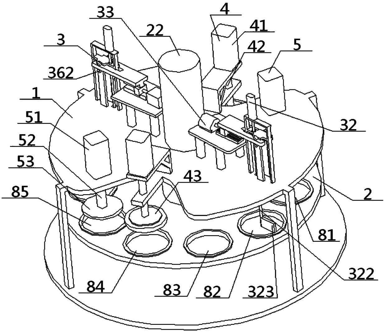
[0053] see Figure 1 to Figure 6, a kind of manufacturing method of upper and lower layer interlayer particle layer class tool, comprises the bottom liner adding process, the middle particle adding process and the top layer liner adding process that are carried out successively, described bottom liner adding process refers to laying the bottom liner, so The intermediate particle addition process refers to laying particles on the top surface of the bottom liner to form a particle layer, and the top liner addition process refers to laying a top liner on the top surface of the particle layer; After the plate addition process, it also includes the heating and condensation process and the pressure forming process in sequence;
[0054] The bottom liner adding process refers to that the bottom liner adding device 6 lays a bottom liner in its corresponding groove; the intermediate particle adding process refers to the bottom layer of the particle adding device 3 in its corresponding g...
Embodiment 2
[0058] Basic content is the same as embodiment 1, the difference is:
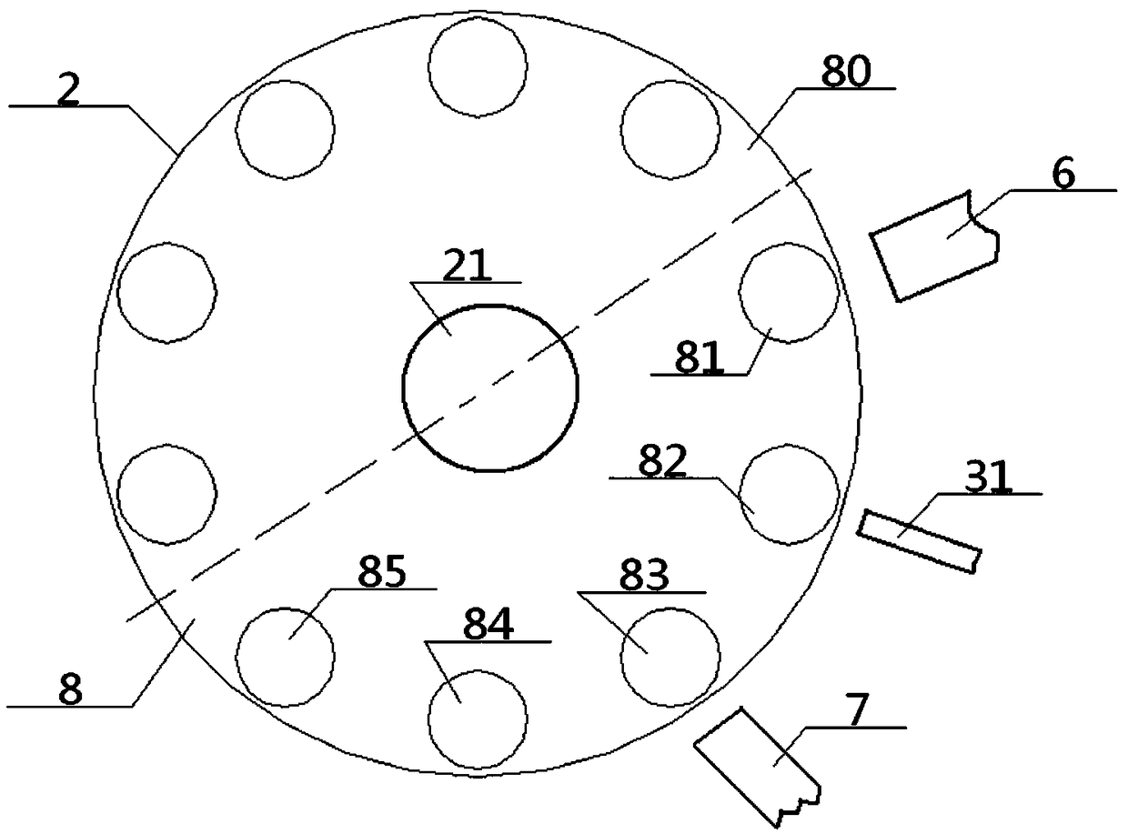
[0059] The disc surface of the rotating flat disk 2 is also provided with at least one auxiliary production area 80, the number and arrangement order of the grooves set in the auxiliary production area 80 are consistent with the main production area 8, and the auxiliary production area 80, the main production area Zones 8 are sequentially arranged along the disk surface; after the manufacturing method starts, the auxiliary production zone 80 rotates together with the main production zone 8, and the five grooves in the auxiliary production zone 80 and the five grooves in the main production zone 8 undergo the same operation, To continuously make molded bodies and cycle in turn.
[0060] In addition, the same number of bottom liner adding devices 6, granule adding devices 3, top liner adding devices 7, heating and coagulation devices 4, and pressure forming devices 5 can be added according to the number of au...
Embodiment 3
[0062] Basic content is the same as embodiment 1, the difference is:
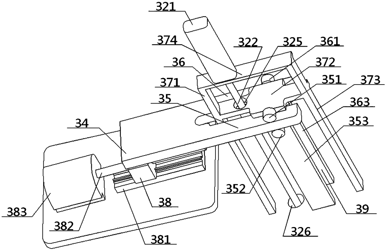
[0063] The particle adding device 3 includes an external adding unit 31, a lifting unit 32 and a horizontal drive unit 33, the discharge port of the external adding unit 31 communicates with the inner cavity of the second groove 82, and the lifting unit 32 includes a lifting motor 321, elevating rod 322 and agitator 323, elevating motor 321 is set higher than fixed flat plate 1, the output end of elevating motor 321 is connected with the top of elevating rod 322, and the bottom end of elevating rod 322 passes through fixed flat plate 1 and connects with Agitator 323 is connected, and agitator 323 is positioned at No. 2 groove 82 just above, and on the elevating rod 322, is positioned at the position between elevating motor 321, fixed plate 1 and is overcoated with horizontal drive platform 324, and this horizontal drive platform 324 and The transverse drive unit 33 carries out reciprocating drive cooperatio...
PUM
 Abstract
Description
Claims
Application Information
PatSnap Eureka turns technology decisions into work you can execute. Powered by our Innovation Knowledge Graph, it runs expert workflows across engineering, life sciences, materials and intellectual property. Get your review-ready output in minutes.


