
Stamping device for automobile electronic components

A technology of stamping device and automotive electronics, applied in the field of automotive parts processing, can solve the problems of stamping of electronic parts that cannot be of different specifications, and achieve the effects of reducing work intensity, saving processing time, and moving smoothly

Active Publication Date: 2019-02-01
刘兆
View PDF5 Cites 0 Cited by
  • Summary
  • Abstract
  • Description
  • Claims
  • Application Information

AI Technical Summary

Problems solved by technology

[0004] The purpose of the present invention is to provide a stamping device for automotive electronic parts to solve the problems in the above-mentioned background technology that electronic parts of different specifications cannot be stamped at the same time.

Method used


Image

  • Stamping device for automobile electronic components
  • Stamping device for automobile electronic components
  • Stamping device for automobile electronic components

Examples


Embodiment Construction

[0025] The following will clearly and completely describe the technical solutions in the embodiments of the present invention with reference to the accompanying drawings in the embodiments of the present invention. Obviously, the described embodiments are only some, not all, embodiments of the present invention.

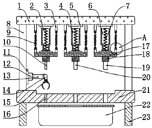
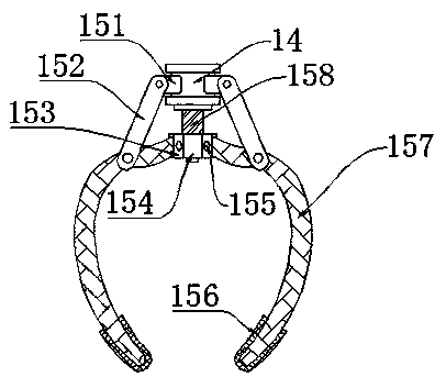
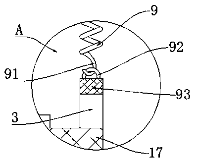
[0026] see Figure 1-4 , an embodiment provided by the present invention: a stamping device for automotive electronic parts, including a console 21, the upper end of the console 21 is provided with a support frame 8, the support frame 8 is used to provide support for the top plate 1, and the support frame 8 A top plate 1 is installed on the top of the top plate, and the top plate 1 is used to install and fix the connecting plate 3 and the mounting plate 5. The lower end of the top plate 1 is provided with a mounting plate 5, and there are three mounting plates 5, and the lower ends of the three mounting plates 5 are respectively provided with the first One piston cyl...


PUM


Abstract

The invention discloses a stamping device for automobile electronic components. The stamping device comprises an operating platform. Mounting plates are arranged at the lower end of a top plate. A first piston cylinder, a second piston cylinder and a third piston cylinder are arranged at the lower ends of the three mounting plates correspondingly. Piston rods are arranged inside the first piston cylinder, the second piston cylinder and the third piston cylinder correspondingly. A stamping rod is mounted at the lower end of each stamping plate. A first stamping head, a second stamping head anda third stamping head are arranged at the lower ends of the stamping rods. A mounting bracket is arranged at the other side of a hydraulic extending-and-contracting rod. A component clamp is mounted at the lower end of the mounting bracket and provided with a sliding rotating shaft seat. Support pillars are mounted at the bottom end of the operating platform. A containing box is arranged below theoperating platform. By means of the stamping device, the automobile electronic components of different specifications can be stamped at the same time and gripped through the component clamp; and theelectronic components are prevented from being damaged.

Description

technical field [0001] The invention relates to the technical field of auto parts processing, in particular to a stamping device for auto electronic parts. Background technique [0002] Cars are widely used means of transportation in daily life. With the updating and improvement of technology, the functions on cars are becoming more and more powerful. To realize these functions, various auto parts are needed. The number of parts reaches tens of thousands. Auto parts processing is the unit that constitutes the overall processing of auto parts and the products that serve the processing of auto parts. As the foundation of the auto industry, auto parts are a necessary factor to support the sustainable and healthy development of the auto industry. Automobile self-owned brands and technological innovation need parts and components as the basis, and the independent innovation of parts and components will generate a strong impetus to the development of the entire vehicle industry, w...

Claims


Application Information

Patent Timeline
Patent Type & Authority Applications(China)
IPC IPC(8): B21D28/02B21D43/10B21D43/20
CPCB21D28/02B21D43/105B21D43/20
Inventor 毛建国刘兆何向东
Owner 刘兆
Learn More