Laser deposition scanning path planning method

A scanning path and laser deposition technology, which is applied in the field of additive manufacturing, can solve the problems of many empty paths of equipment, high overlap rate of scanning paths, and heavy workload.

Inactive Publication Date: 2019-02-01
TSC LASER TECH DEV BEIJING CO LTD
View PDF10 Cites 5 Cited by
  • Summary
  • Abstract
  • Description
  • Claims
  • Application Information

AI Technical Summary

Problems solved by technology

[0002] After the parts are layered and sliced, the program automatically sorts the cutting areas of each slice layer. The default sorting method is irregular, and there are many empty paths of the equipment. Some areas have serious heat accumulation, which affects the forming speed, efficiency and quality, it is necessary to manually...

Method used


Image

  • Laser deposition scanning path planning method
  • Laser deposition scanning path planning method
  • Laser deposition scanning path planning method

Examples


Embodiment Construction

[0031] The specific implementation manners according to the present invention will be described below in conjunction with the accompanying drawings.

[0032] In the following description, many specific details are set forth in order to fully understand the present invention, but the present invention can also be implemented in other ways different from those described here, therefore, the present invention is not limited to the specific embodiments disclosed below limit.

[0033] In order to solve the problems of low forming efficiency and poor quality of parts, the present invention provides a laser deposition scanning path planning method.

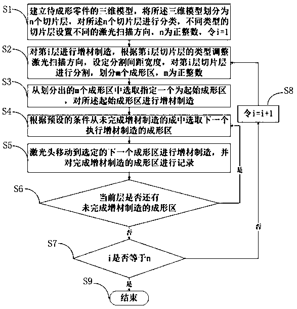
[0034] Such as figure 1 As shown, a laser deposition scanning path planning method provided by the present invention is characterized in that it includes the following steps:

[0035] S1. Establish a three-dimensional model of the part to be formed, divide the three-dimensional model into n slice layers, classify the n slice layers, se...


PUM


Abstract

The invention relates to a laser deposition scanning path planning method. The method comprises the steps that forming zones for performing additive manufacturing are selected by means of two standards of a temperature value and distance; sequential order of the forming zones is controlled for avoiding ineffective strokes, lowering heat input to the maximum extent and improving the forming efficiency; and the scanning direction of a laser head is adjusted by 90 degrees for additive manufacturing, so that the associative property between layers is enhanced, and the quality of parts is improved.

Description

technical field [0001] The invention relates to the technical field of additive manufacturing, in particular to a laser deposition scanning path planning method. Background technique [0002] After the parts are layered and sliced, the program automatically sorts the cutting areas of each slice layer. The default sorting method is irregular, and there are many empty paths of the equipment. Some areas have serious heat accumulation, which affects the forming speed, efficiency and Quality requires manual adjustment of the order of the cutting areas, which requires a lot of work, and the scanning trajectory overlap rate between the original layer and the copied layer is high, which affects the combination between the original layer and the copied layer. Therefore, the traditional method has the problems of low forming efficiency and poor part quality. Contents of the invention [0003] In view of the above technical problems, the present invention provides a laser deposition...

Claims


Application Information

Patent Timeline
IPC IPC(8): B22F3/105B33Y50/02B28B1/00B29C64/153B29C64/386
CPCB28B1/001B29C64/153B29C64/386B33Y50/02B22F10/00B22F10/36B22F10/85B22F10/20Y02P10/25
Inventor 王越岭葛青刘斌高佩宝
Owner TSC LASER TECH DEV BEIJING CO LTD
Why Eureka
Try Eureka