
Electric baby carriage

An electric baby carriage and driving mechanism technology, applied in the field of baby carriages, can solve the problems of complex control process, high use cost, unfavorable promotion and application of electric baby carriages, etc., and achieve the effects of simple control process, low use cost and ingenious structure

Pending Publication Date: 2019-02-01
PINGHU KEYUAN TECH SERVICE
View PDF0 Cites 0 Cited by
  • Summary
  • Abstract
  • Description
  • Claims
  • Application Information

AI Technical Summary

Problems solved by technology

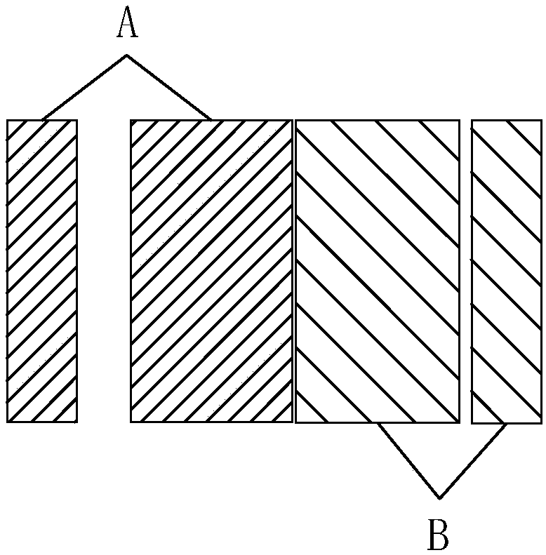
[0003] In order to further enhance the fun of electric baby carriages and increase the market share of electric baby carriages, existing electric baby carriages generally have a swing function, and the clutch is usually used to realize the function conversion between the swing function of the baby carriage and the forward and backward of the baby carriage. The traditional clutch structure usually It is the main body of the clutch and the clutch plate to realize the clutch function, but when it comes to function switching, when it is necessary to switch from one state to another, two clutches are required to cooperate, such as image 3 As shown, the A clutch and the B clutch, when working normally, the A clutch is separated, the B clutch is closed, and the clutch plate in B realizes the forward and backward functions of the electric stroller; when the swing function needs to be realized, the A clutch is closed, and the B clutch is separated. The clutch plate in A realizes the swing function of the electric stroller. This method is expensive to use and the control process is complicated, which is not conducive to the promotion and application of electric strollers in the market.

Method used


Image

  • Electric baby carriage
  • Electric baby carriage
  • Electric baby carriage

Examples


Embodiment

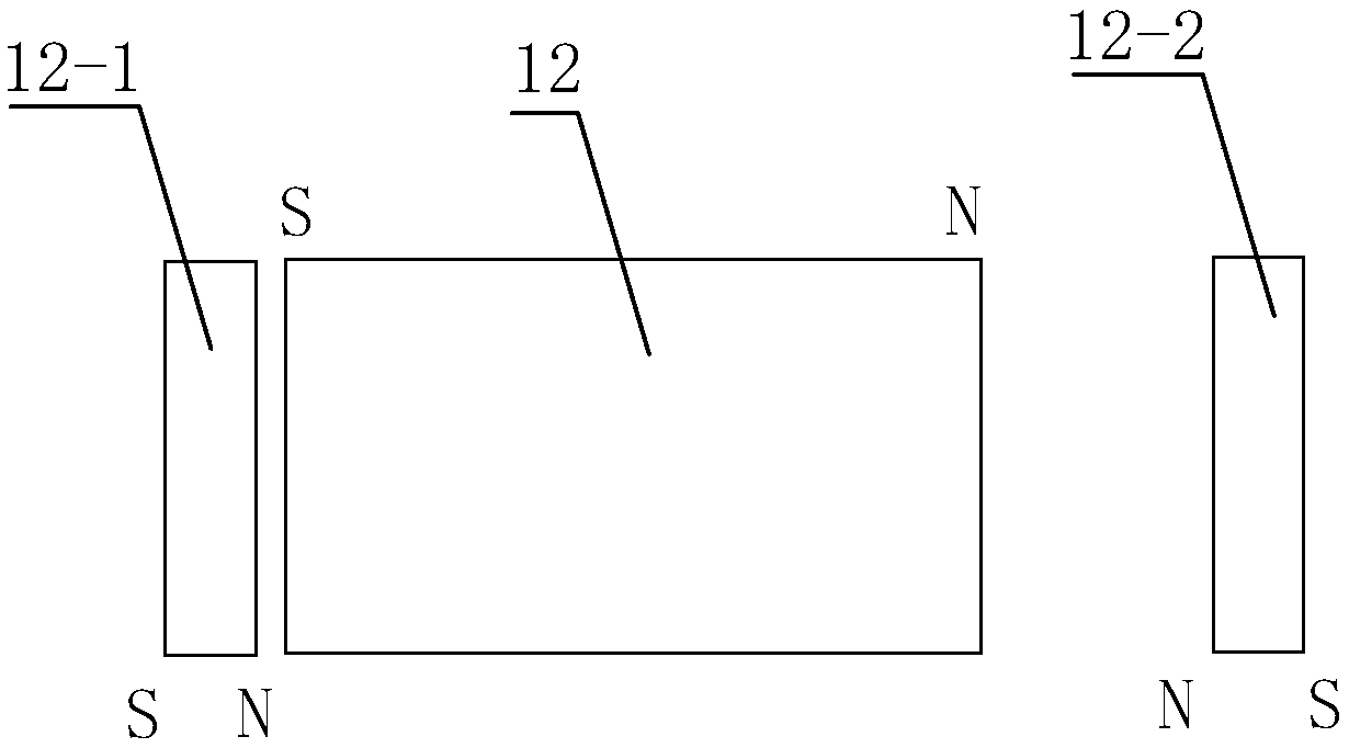
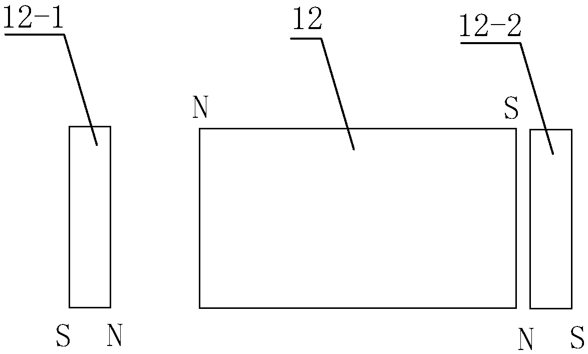
[0028] Example: such as Figure 1 to Figure 11 As shown, the electric stroller is mainly used in electric strollers, including a drive mechanism, a connecting mechanism, and a swing mechanism. The drive mechanism is mainly used to drive the swing mechanism so that the electric stroller realizes the swing function. The connecting mechanism is connected between the drive mechanism and the swing mechanism. In the meantime, the stability of the swing mechanism in the swing process is ensured, and the swing mechanism enables the electric stroller to realize the swing function, which enhances the fun of the electric stroller.

[0029] Existing baby strollers generally have a swing function. The swing function is realized by a swing motor under the seat of the electric stroller and a crank arm type rear axle. If a child with a heavier weight sits on the stroller, the motor is easily damaged when a single motor drives the swing. It may even be unable to swing. Usually, the increase of sw...


PUM


Abstract

The invention relates to an electric baby carriage. The electric baby carriage comprises a driving mechanism, a connecting mechanism and a swinging mechanism; the connecting mechanism is mounted between the driving mechanism and the swinging mechanism; the swinging mechanism comprises a swinging gear and a driving gear; the swinging gear and the driving gear are arranged in parallel; a swinging gear shaft is eccentrically mounted on a crank arm rear shaft; the connecting mechanism comprises a functional gear; a functional gear shaft penetrates into the functional gear; the electric baby carriage further comprises a clutch device; the clutch device comprises a clutch sheet body, a first clutch sheet and a second clutch sheet; the clutch sheet body, the first clutch sheet and the second clutch sheet all have N magnet pole faces and S magnet pole faces; and the clutch device drives the functional gear. By arranging the clutch device as the clutch sheet body, the first clutch sheet and thesecond clutch sheet with the N magnet pole faces and the S magnet pole faces, the clutch has the advantages of skillful structure, simple control process and low use cost, and the clutch is beneficial for the electric baby carriage to be popularized and applied on the market.

Description

Technical field [0001] The invention relates to the technical field of baby carriages, in particular to electric baby carriages. Background technique [0002] Baby strollers are one of the main categories of children’s toys, including children’s bicycles, strollers, baby walkers, children’s tricycles, and children’s electric toy cars. In recent years, children’s electric toy cars, also known as electric strollers, are active in various domestic In cultural activity squares and living quarters in large, medium and small cities, as a simulation driving tool, electric strollers can exercise children’s sense of direction and learn and imitate adult car driving skills. It can improve children’s hand, eye, and brain perception capabilities while at the same time Without losing interest, it is currently being favored by more and more young Chinese parents. Compared with non-electric strollers such as strollers and baby walkers, electric strollers are unique in that they are driven by bu...

Claims


Application Information

Patent Timeline
IPC IPC(8): B60K17/02F16D27/08
CPCF16D27/08B60K17/02
Inventor 马水根陶杰王燕胡晓琴马思晨马丹刘悦黄依娇
Owner PINGHU KEYUAN TECH SERVICE
Learn More