
Hydraulic drip irrigation tape recycling machine

A technology of drip irrigation belt and recycling machine, which is applied in the direction of conveying filamentous materials, thin material processing, transportation and packaging, etc. It can solve the problems of wasting time and manpower, delaying spring planting, and being unable to remove quickly, so as to save costs and reduce labor effect

Inactive Publication Date: 2019-02-01
张玉来
View PDF0 Cites 0 Cited by
  • Summary
  • Abstract
  • Description
  • Claims
  • Application Information

AI Technical Summary

Problems solved by technology

[0002] At present, due to the lack of water resources, drip irrigation and water-saving projects are implemented in large areas in rural areas, which are suitable for various crops, not only to achieve the purpose of water saving, but also to increase crop yields. Work, all rely on manpower to recycle, waste time, labor cost is too high, to delay the spring sowing of the second year; and the current drip irrigation water-saving project is expanding in a large area, the capillary recycling of drip irrigation belt is the primary problem to be solved, the current drip irrigation belt recycling machine is in After recycling the drip irrigation tape, the drip irrigation tape is coiled on the reel and cannot be removed quickly, wasting time and manpower

Method used


Image

  • Hydraulic drip irrigation tape recycling machine
  • Hydraulic drip irrigation tape recycling machine
  • Hydraulic drip irrigation tape recycling machine

Examples


Embodiment 1

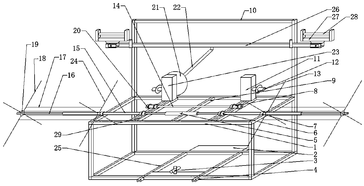
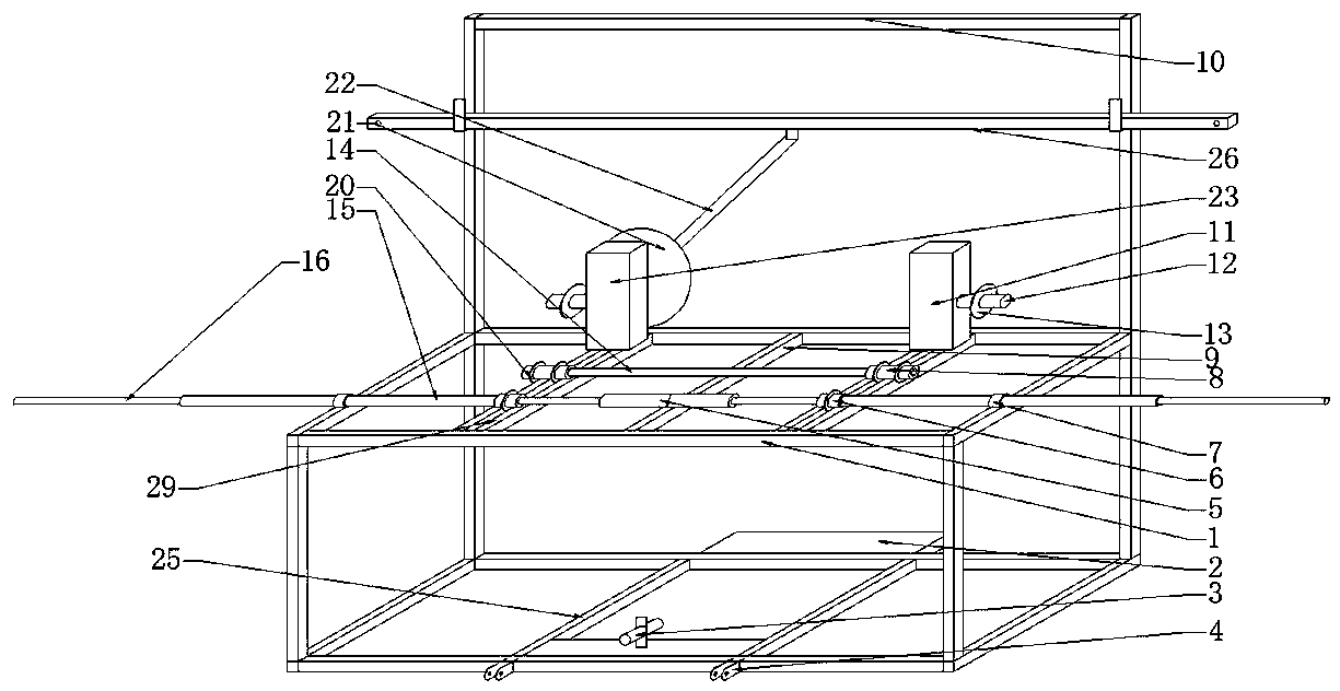
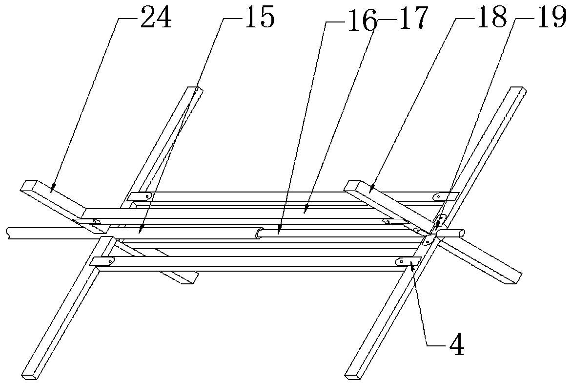
[0016] Example 1, such as Figure 1~Figure 4 As shown, a hydraulic drip irrigation belt recovery machine includes an iron frame 1, the top of the iron frame 1 is provided with a handrail 10, the lower side of the handrail 10 is provided with a support rod 26, and the two ends of the support rod 26 are provided with a support Frame 27, the upper part of the support frame 27 is provided with a rotating shaft 28, the middle part of the iron frame 1 is provided with an upper beam 9, the bottom of the iron frame 1 is provided with a lower beam 25, an iron plate is arranged between the lower beams 25, and a hydraulic gear pump is arranged on the iron plate 3. The front part of the iron frame 1 is provided with an ear plate 4, the rear part of the iron frame 1 is provided with a standing plate 2, the upper part of the iron frame 1 is provided with a fixed ring 7, and the upper beam 9 is provided with a hydraulic cylinder 5, which includes a left The hydraulic cylinder and the right h...


PUM


Abstract

The invention belongs to a hydraulic drip irrigation tape recycling machine. The hydraulic drip irrigation tape recycling machine comprises an iron frame, wherein an armrest beam is arranged at the top end of the iron frame, an upper cross beam is arranged in the middle of the iron frame, lower cross beams are arranged at the bottom of the iron frame, an iron plate is arranged between the lower cross beams, a hydraulic gear pump is arranged above the iron plate, fixing rings are arranged on the upper part of the iron frame, hydraulic cylinders are arranged on the upper cross beam, frame platesare arranged on the two sides of the upper cross beam, a gearbox is arranged at the rear part of the left side frame plate, a hydraulic motor is arranged at the rear part of the right side frame plate, transmission rings a are arranged in the middles of the frame plates, transmission rings b are arranged at the front parts of the frame plates, a transmission rod a is arranged between the transmission rings a, the transmission rings b are connected with transmission rods b, the transmission rods b are of a hollow structure, the transmission rods b penetrate out of the fixing rings, the hydraulic cylinders are connected with transmission rods c, the transmission rods c penetrate out of the transmission rods b, and reels are arranged on the two sides of the iron frame. According to the machine, the hydraulic cylinders can enable the transmission rods c to move left and right in the transmission rods b, so that a drip irrigation tape wound around the reels can be conveniently taken down,the labor force is reduced, and the cost is saved.

Description

technical field [0001] The invention belongs to the field of agricultural machinery, in particular to a hydraulic drip irrigation belt recycling machine. Background technique [0002] At present, due to the lack of water resources, drip irrigation and water-saving projects are implemented in large areas in rural areas, which are suitable for various crops, not only to achieve the purpose of water saving, but also to increase crop yields. Work, all rely on manpower to recycle, waste time, labor cost is too high, to delay the spring sowing of the second year; and the current drip irrigation water-saving project is expanding in a large area, the capillary recycling of drip irrigation belt is the primary problem to be solved, the current drip irrigation belt recycling machine is in After recycling the drip irrigation tape, the drip irrigation tape is coiled on the reel and cannot be removed quickly, wasting time and manpower. Contents of the invention [0003] The purpose of ...

Claims


Application Information

Patent Timeline
IPC IPC(8): B65H54/74B65H67/04
CPCB65H54/74B65H67/04B65H2701/333
Inventor 张玉来
Owner 张玉来
Learn More