
Internal centralized transverse prestress restraint masonry and prestress applying method thereof

A horizontal prestressing and centralized technology, which is applied in the processing of walls, buildings, and building materials, can solve the problems of poor seismic performance, high cost, and affecting the appearance of buildings, and achieve convenient construction, sufficient material supply, and mature construction technology Effect

Inactive Publication Date: 2019-02-01
CHONGQING UNIV
View PDF6 Cites 1 Cited by
  • Summary
  • Abstract
  • Description
  • Claims
  • Application Information

AI Technical Summary

Problems solved by technology

[0006] The purpose of the present invention is to provide a laterally prestressed constrained masonry with convenient construction and clear action mechanism to solve the problems that the existing technology cannot effectively improve the characteristics of the masonry material, poor seismic performance, affect the appearance of the building, and have high costs.

Method used


Image

  • Internal centralized transverse prestress restraint masonry and prestress applying method thereof
  • Internal centralized transverse prestress restraint masonry and prestress applying method thereof

Examples


Embodiment 1

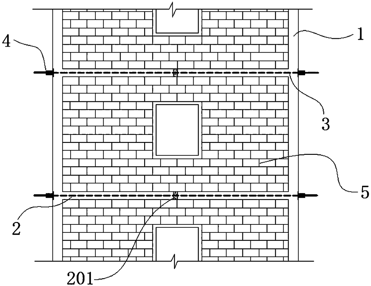
[0026] This embodiment discloses a built-in centralized lateral prestressed constrained masonry, which includes a house masonry provided with concrete structural columns 1 and concrete horizontal ring beams 2 . The concrete structural column 1 and the concrete horizontal ring beam 2 are cast-in-situ connected to jointly strengthen the integrity of the building.

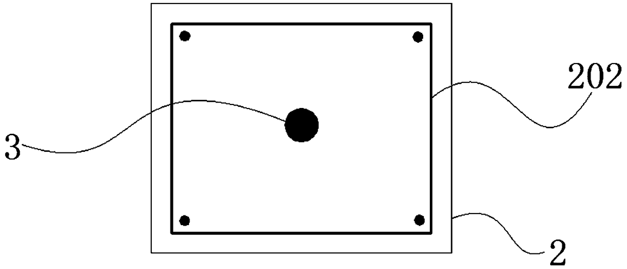
[0027] see figure 1 and figure 2 , the steel cage 202 of the concrete horizontal ring beam 2 is arranged with unbonded prestressed tendons 3 . The unbonded prestressed steel tendons 3 are arranged along the vertical and horizontal masonry walls of the house, forming a closed shape along the vertical and horizontal walls on the same floor. The tension end of the unbonded prestressed tendon 3 is arranged outside the concrete construction column 1 . The unbonded prestressed tendons 3 are prestressed at the tension end and anchored by prestressed anchors 4 .

[0028] The unbonded prestressed steel tendons 3 produce a...

Embodiment 2

[0031] A method for applying prestress to the built-in centralized transverse prestress constraint masonry according to claim 1, comprising the following steps:

[0032] 1) When binding the steel bars of the ring beam, the unbonded prestressed steel tendons 3 are concentratedly arranged in the reinforcement cage 202 of the concrete horizontal ring beam 2 .

[0033] 2) Concrete horizontal ring beam 2 is poured, and post-cast section 201 is reserved on the beam body of concrete horizontal ring beam 2 . Wherein, the width of the post-casting section 201 is 100mm-250mm, which meets the quality requirements of post-casting concrete.

[0034] 3) After the concrete of the concrete horizontal ring beam 2 reaches the design strength, the tensioning work of the unbonded prestressed tendons 3 is carried out.

[0035] 4) After the tensioning is completed, the concrete in the post-casting section 201 is poured, and the exposed prestressed anchor 4 is closed.


PUM

PropertyMeasurementUnit
Widthaaaaaaaaaa

Abstract

The invention provides internal centralized transverse prestress restraint masonry and a prestress applying method thereof. The internal centralized transverse prestress restraint masonry comprises house masonry provided with concrete structural columns and concrete horizontal ring beams. Unbonded prestressing tendons are arranged in reinforcement cages of the concrete horizontal ring beams, applyprestress at the tension ends and are anchored by prestressed anchorage devices. The prestress applying method of the internal centralized transverse prestress restraint masonry comprises the steps that the unbonded prestressing tendons are arranged, concrete of the horizontal ring beams is poured, and the unbonded prestressing tendons are tensioned. A prestress transmitting route of the transverse prestress restraint masonry is clear, and the action mechanism is facilitated to be clear. The cracking load, the ultimate deformation capability and the energy dissipation capability of a house masonry wall are improved significantly, when damaged, the house masonry wall cracks but is not scattered, and thus good integrity and good collapse resistance are maintained.

Description

technical field [0001] The invention relates to the anti-seismic field of masonry structures, in particular to a prestressed constrained masonry. Background technique [0002] Masonry has the advantages of superior economic performance, simple construction, and unique shape, and is widely used in house construction in our country. Due to the weak bond between the mortar and the blocks that make up the masonry, the tensile, flexural and shear strength of the masonry is low, resulting in poor seismic performance. Seriously limit the application of masonry houses in earthquake zones. According to the new version of the earthquake zoning map launched in June 2016, undefended areas have been cancelled. Therefore, it is urgent to take effective technical measures to improve the seismic performance of building masonry. [0003] At present, the commonly used technical schemes mainly include adding concrete ring beams and structural columns and applying prestress to building mason...

Claims


Application Information

Patent Timeline
IPC IPC(8): E04B2/64E04G21/12
CPCE04B2/64E04G21/12
Inventor 秦士洪陈鹏饶邦高峰张兴伟
Owner CHONGQING UNIV
Learn More