Hydroelectric power system and hydroelectric power station

A technology of generating sets and waterwheels, which is applied in the direction of hydroelectric power generation, water wheels, engine components, etc., can solve the problems of inconvenient shipping and achieve the effects of small footprint, low construction difficulty, and simple structure

Pending Publication Date: 2019-02-01
汪顺宝
View PDF0 Cites 0 Cited by
  • Summary
  • Abstract
  • Description
  • Claims
  • Application Information

AI Technical Summary

Problems solved by technology

[0002] Most of the hydroelectric power stations in our country are power stations that build dams. There are usually many hidden

Method used


Image

  • Hydroelectric power system and hydroelectric power station

Examples


Embodiment

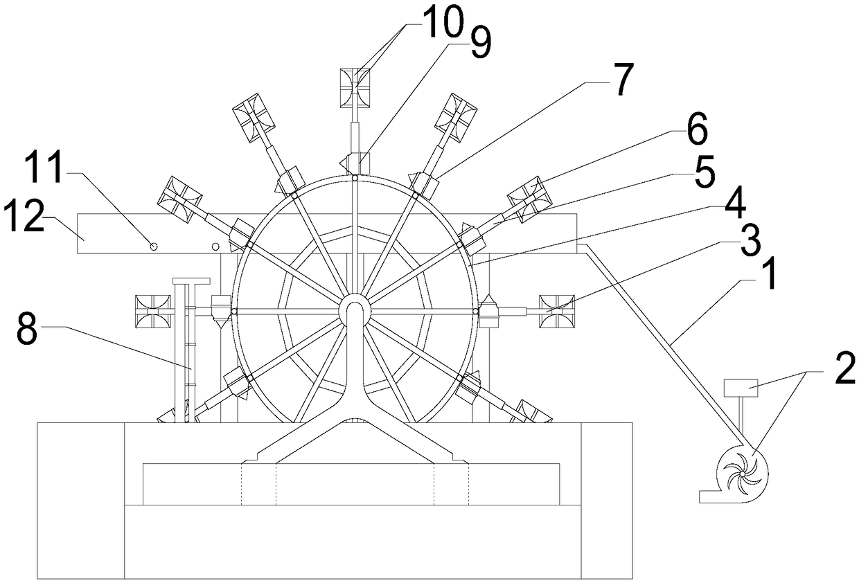
[0019] combine figure 1 , the present embodiment discloses a hydroelectric power generation system and a hydroelectric power station, comprising a waterwheel main body, a generator set 2, a pumping mechanism reservoir 12 and a control system; The water receiving bucket 7 on the frame 4, the umbrella-shaped two-way water bucket 6, the extension shaft 5 and the rotation shaft 3, the rotation shaft 3 is connected to the extension shaft 5 and the umbrella-shaped two-way water bucket 6, and the extension shaft 5 is connected to the waterwheel frame 4 Fixedly connected, the reservoir 12 is connected to the generator set 2 through the pipeline 1; the control system is electrically connected to the rotating shaft 3.

[0020] In this embodiment, the extension shaft 5 is arranged beside the water receiving bucket 7 and is perpendicular to the side of the water receiving bucket 7. The water receiving bucket 7 is a combination of a cone and a cylinder. The direction of the water flow is ...


PUM


Abstract

The invention discloses a hydraulic power system and a hydraulic power station. According to the hydroelectric power system and the hydraulic power station using the hydroelectric power system, dam construction is not required, water transportation is completed by a water truck and water storage is completed by an impounding reservoir, the occupied area is small, ecological protection is facilitated, and movement of ships are not affected.

Description

technical field [0001] The invention relates to the field of power generation systems, in particular to a system for generating hydropower by using a waterwheel and a hydropower station including the power generation system. Background technique [0002] Most of the hydroelectric power stations in our country are power stations that build dams. There are usually many hidden dangers in the hydroelectric power stations where dams are built, and water storage through dams brings great inconvenience to shipping. Contents of the invention [0003] The object of the present invention is to provide a hydroelectric power generation system and a hydroelectric power station for solving the above problems. [0004] For this reason, a kind of hydropower generation system provided by the present invention and the hydroelectric power station adopting this power generation system do not need to build dams, and use water trucks and reservoirs to complete water transportation and water sto...

Claims


Application Information

Patent Timeline
IPC IPC(8): F03B13/06F03B7/00F04B19/10
CPCF03B7/003F03B13/06F04B19/10Y02E10/20Y02E60/16
Inventor 汪凤姣汪顺宝
Owner 汪顺宝
Why Eureka
Try Eureka