A concealed waterway control box and shower
A waterway control and concealed installation technology, which is applied to valve devices, valve operation/release devices, valve details, etc., can solve the problems of long wall hitting time, large thickness of pre-embedded structure, long time consumption, etc. The effect of reducing the construction time and reducing the depth of the buried wall
- Summary
- Abstract
- Description
- Claims
- Application Information
AI Technical Summary
Problems solved by technology
Method used
Image
Examples
Embodiment 1
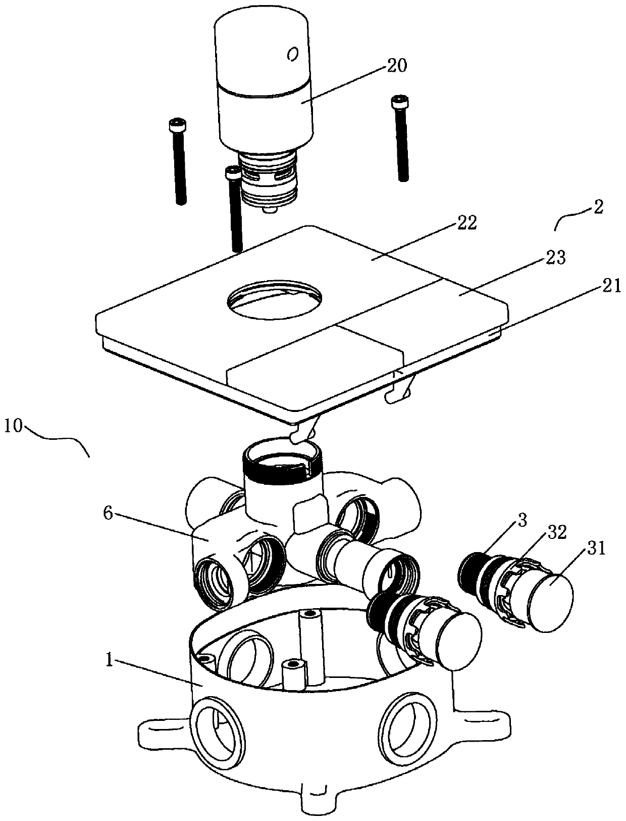
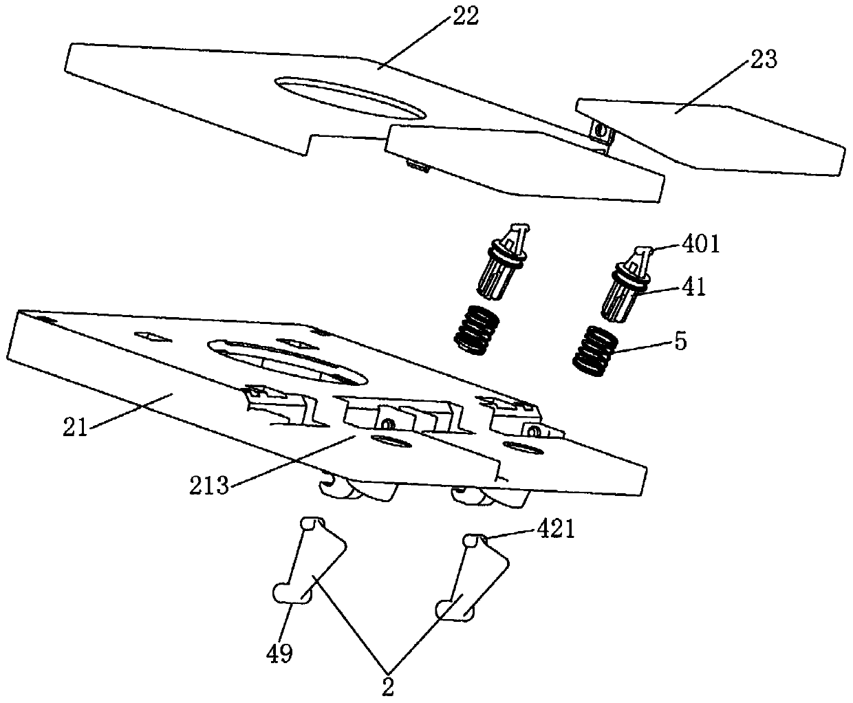
[0056] Such as Figure 2 to Figure 8 As shown, the driving unit 4 includes a first driving member 41 and a lever 42, the first driving member 41 is slidably arranged on the cover unit 2, and one end of the first driving member 41 extends into the housing 1 for abutting against the lever 42, the other end of which extends out of the bottom plate 21 to form a driving end 48 for external force. In this embodiment, the first driving member 41 is slidably mounted on the bottom plate 21 and is a rod-shaped structure.
[0057] The lever 42 is hinged in the housing 1, and it is pushed and rotated by the first driving member 41 to form the above-mentioned conversion structure, and the side of the lever 42 abutting against the pressing cover 31 of the button valve core 3 constitutes the above-mentioned pushing end 49, reset The member 5 is arranged between the first driving member 41 and the cover unit 2 .
[0058] Preferably, the end face of the pressing end cover of the key valve cor...
Embodiment 2
[0065] Such as Figure 9 As shown, the driving unit 4 includes a second driving member 43, a guide tube 44, and a thread-like resisting member 45 pierced in the guide tube 44. The second driving member 43 is slidably arranged on the bottom plate 21, and one end of it protrudes from the bottom plate. 21 forms the above-mentioned drive end 48 to be driven by an external force, and its other end is fixedly connected to the push piece 45 to apply a drive force thereto; in this embodiment, the installation method of the button valve core 3 is consistent with that of Embodiment 1, The end face of the pressing end cap faces downwards, and the driving end 48 of the second driving member 43 is lower than the end face of the pressing cap 31 of the button valve core 3 .
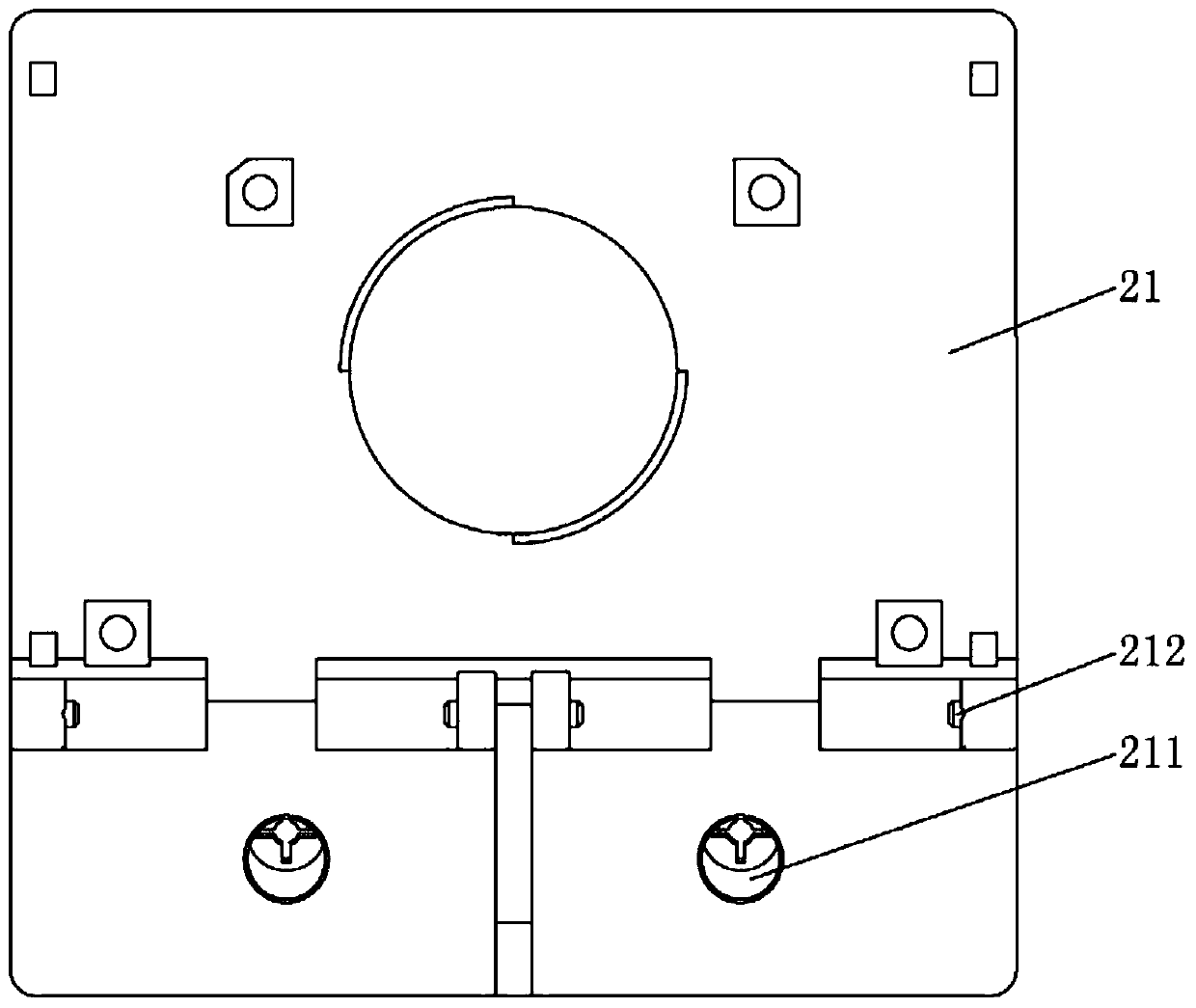
[0066] Specifically, the second driving member 43 is slidably arranged on the slideway 211 of the bottom plate 21, and one end of which is fixedly connected with the pushing member 45 is arranged in the slideway 211, an...
Embodiment 3
[0071] Such as Figure 10 and Figure 11 As shown, the driving unit 4 in this embodiment includes a third driving member 46 and a rotating member 47. The third driving member 46 is slidably arranged on the bottom plate 21, and one end thereof protrudes from the bottom plate 21 to form the above-mentioned driving end 48 for driving by external force. , the other end of which extends into the casing 1; in this embodiment, the installation method of the key valve core 3 is consistent with that of the embodiment 1, the end face of which presses the end cover faces downward, and the driving end 48 of the third driving member 46 The end surface of the pressing cover 31 is lower than the key valve core 3 .
[0072] Specifically, the third driving member 46 is slidably arranged on the slideway 211 of the bottom plate 21, and a rack surface 461 is formed at one end of the driving member 46 protruding into the housing 1. The reset member 5 is installed in the slideway 211, and its two ...
PUM
 Abstract
Description
Claims
Application Information
 - R&D
- Intellectual Property
- Life Sciences
- Materials
- Tech Scout
- Unparalleled Data Quality
- Higher Quality Content
- 60% Fewer Hallucinations
Browse by: Latest US Patents, China's latest patents, Technical Efficacy Thesaurus, Application Domain, Technology Topic, Popular Technical Reports.
© 2025 PatSnap. All rights reserved.Legal|Privacy policy|Modern Slavery Act Transparency Statement|Sitemap|About US| Contact US: help@patsnap.com


