An output voltage detection circuit

A technology of output voltage detection and detection circuit, which is applied in the direction of voltage/current isolation, measuring current/voltage, output power conversion device, etc., and can solve the problem of low sampling accuracy

Active Publication Date: 2020-10-27
SHANGHAI SANSI ELECTRONICS ENG +2
View PDF4 Cites 1 Cited by
  • Summary
  • Abstract
  • Description
  • Claims
  • Application Information

AI Technical Summary

Problems solved by technology

[0009] In view of the shortcomings of the prior art described above, the purpose of the present invention is to provide an output voltage detection circuit for solving the problem of low sampling accuracy due to sampling time when detecting the output voltage of the primary side feedback power supply in the prior art. question

Method used


Image

  • An output voltage detection circuit
  • An output voltage detection circuit
  • An output voltage detection circuit

Examples


Embodiment Construction

[0041] Embodiments of the present invention are described below through specific examples, and those skilled in the art can easily understand other advantages and effects of the present invention from the content disclosed in this specification. The present invention can also be implemented or applied through other different specific implementation modes, and various modifications or changes can be made to the details in this specification based on different viewpoints and applications without departing from the spirit of the present invention. It should be noted that, in the case of no conflict, the following embodiments and features in the embodiments can be combined with each other.

[0042]It should be noted that the diagrams provided in the following embodiments are only schematically illustrating the basic ideas of the present invention, and only the components related to the present invention are shown in the diagrams rather than the number, shape and shape of the compon...


PUM


Abstract

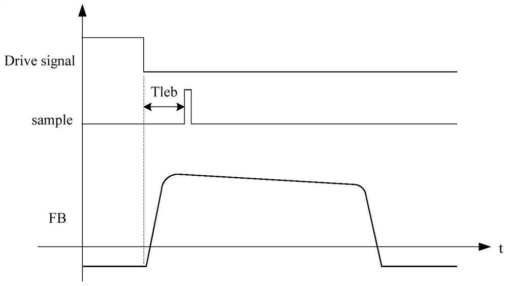
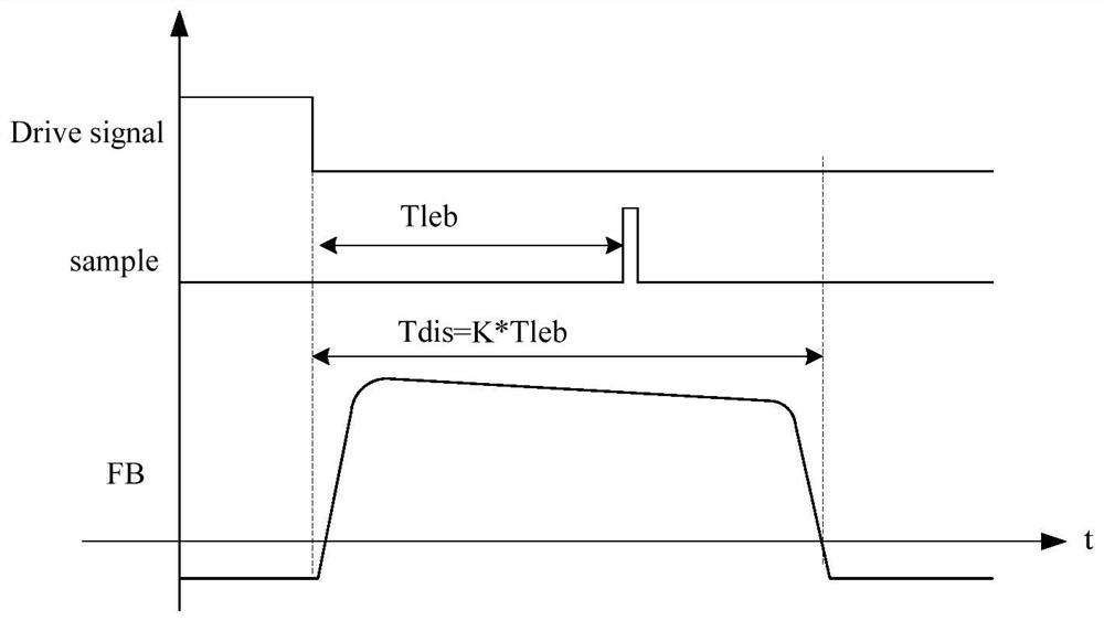
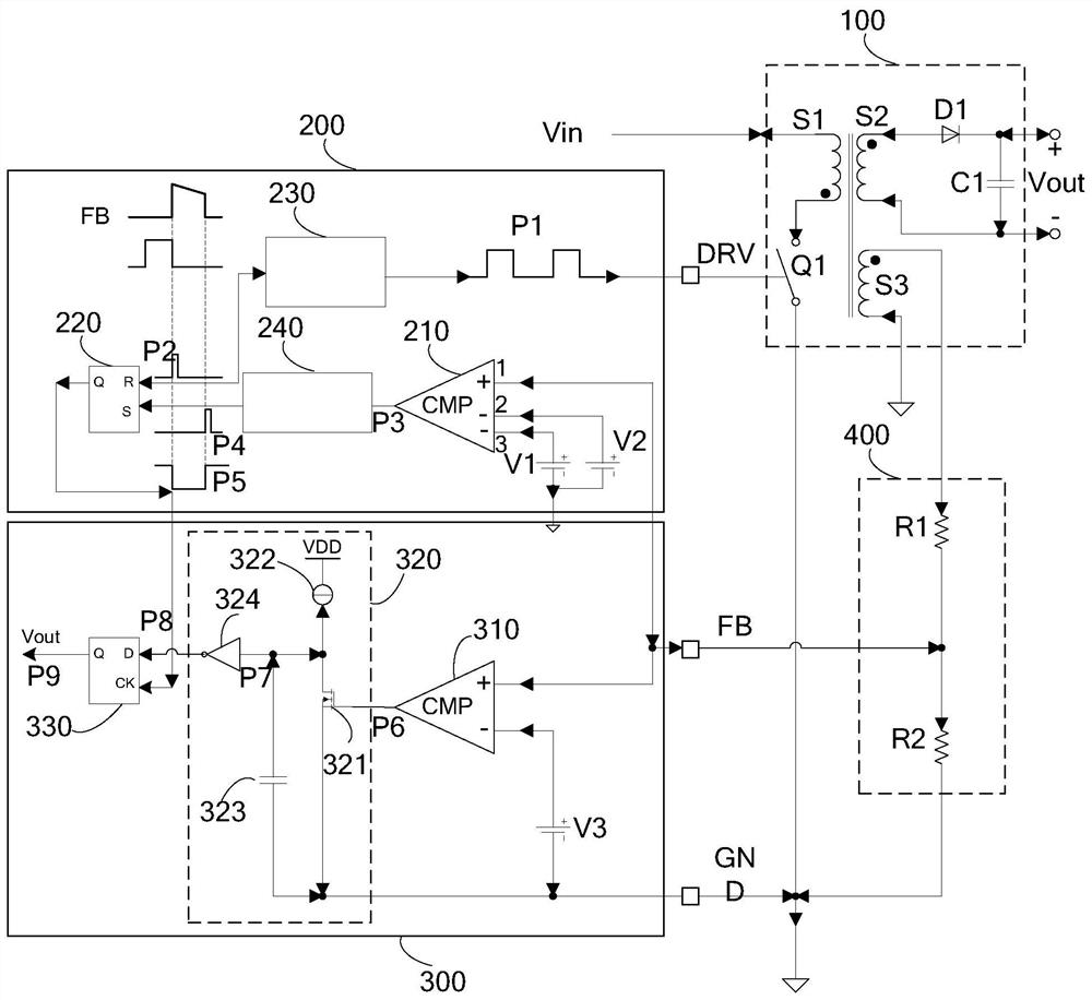
The invention provides an output voltage detection circuit. The output voltage detection circuit comprises a flyback transformer, a discharging detection circuit, a pulse generator, a RS trigger and an output voltage detection circuit, wherein the discharging detection circuit comprises a first comparator, the first comparator is used for sampling to acquire a voltage when a secondary winding is discharged and comparing the voltage with a first reference voltage, the pulse generator is used for generating a pulse signal according to a comparison result of the comparator and a periodic drivingsignal, the RS trigger is used for outputting a level signal of indicating whether discharging of the secondary winding is ended or not according to the pulse signal, the output voltage detection circuit comprises a second comparator, a delay circuit and a D trigger, the second comparator is used for sampling a voltage when the secondary winding is discharged and comparing the voltage with a second reference voltage, the delay circuit is used for delaying an output of the second comparator, and the D trigger is used for locking an output signal of the delay circuit according to the level signal, indicating the discharging ending of the secondary winding, output from the RS trigger and outputting a voltage, acquired by sampling, of the flyback transformer after delay time and before delay time of the delay circuit. By the output voltage detection circuit, the output voltage state can be detected after the secondary winding is approximate to complete discharging.

Description

technical field [0001] The present invention relates to the technical field of electronic circuits, in particular to the technical field of primary-side feedback power supply, in particular to an output voltage detection circuit. Background technique [0002] The primary-side feedback power supply, especially the primary-side feedback flyback power supply, omits the secondary feedback circuit, has a simple structure and low cost, and is widely used. The primary side feedback power supply uses a coupled winding to detect the output voltage. During normal operation, the secondary winding discharges during the switch off period. At this time, the voltage across the secondary winding is the output voltage Vout plus the conduction voltage V of the output rectifier diode. D . The voltage at both ends of the secondary winding can be coupled by using the third winding wound on the same magnetic core, so the output voltage can be detected by sampling the voltage of the third winding...

Claims


Application Information

Patent Timeline
Patent Type & Authority Patents(China)
IPC IPC(8): G01R15/18G01R19/165H02M3/335
CPCG01R15/185G01R19/16576H02M3/33507
Inventor 陈鸣关彦青程爱群郭惠民
Owner SHANGHAI SANSI ELECTRONICS ENG
Why Eureka
Try Eureka