
Method for automatically picking S wave phase with improved skewness

A technology of automatic picking and skewness, which is applied in seismic signal processing and other directions, and can solve problems such as difficulty in accurately determining extreme points, picking errors, and result errors.

Inactive Publication Date: 2019-02-01
LIAONING TECHNICAL UNIVERSITY
View PDF3 Cites 1 Cited by
  • Summary
  • Abstract
  • Description
  • Claims
  • Application Information

AI Technical Summary

Problems solved by technology

The problem is that the skewness curve generally fluctuates and decreases, and there will be many extreme points during the period. Manual analysis and picking can determine the extreme points we need, but if automatic picking is performed by a computer, it is very difficult It is difficult to accurately determine which extreme point we need, which is an important reason for picking errors; they believe that the maximum slope of the curve before the extreme point is when the seismic P wave phase arrives, but according to our research, the P wave seismic phase When the seismic phase with the S wave arrives, it is often after the maximum slope of the curve; they have performed a 5-30Hz band-pass filter on the record before picking up, and then calculated the skewness of the filtered record, but after filtering, the seismic wave When the phase arrives, it will deviate from the original position, and the picked result will also have a large error

Method used


Image

  • Method for automatically picking S wave phase with improved skewness
  • Method for automatically picking S wave phase with improved skewness
  • Method for automatically picking S wave phase with improved skewness

Examples


Embodiment Construction

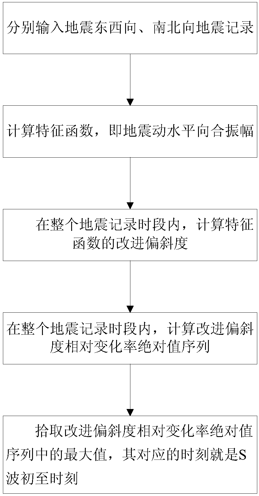
[0050] The invention will be further described below in conjunction with the accompanying drawings and specific implementation examples, a method of automatically picking up S-wave seismic phases that improves the skewness, such as figure 1 As shown, the specific process is as follows:

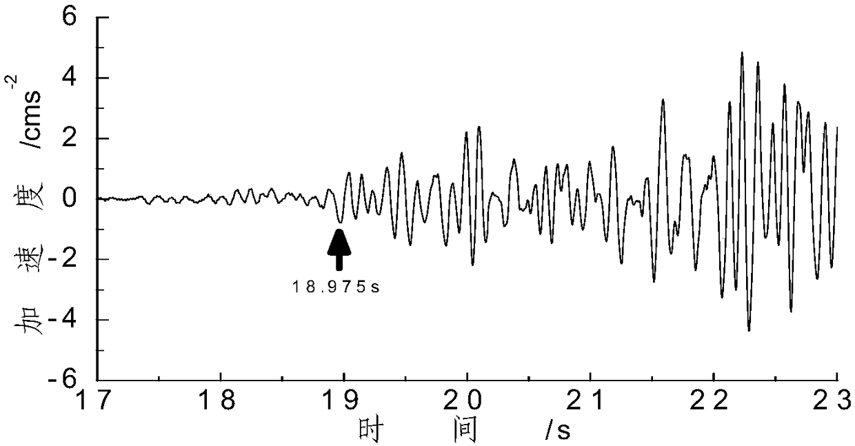
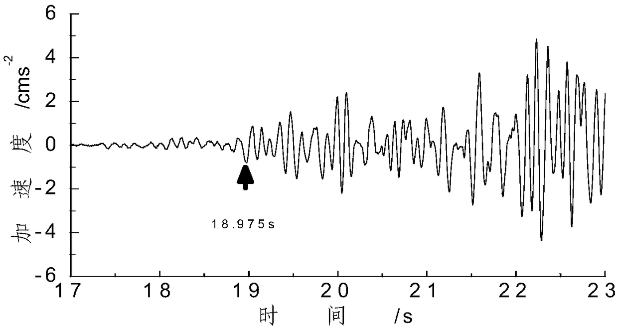
[0051] Step 1: Input earthquake records in east-west direction and north-south direction respectively, where x EW (t) means east-west seismic records, such as image 3 shown, with x NS (t) represents the north-south earthquake record, such as figure 2 shown;

[0052] Step 2: According to the east-west and north-south earthquake records, use the formula (1) to calculate the characteristic function x i (t), that is, the combined horizontal amplitude of ground motion, where, x EW (t) is the east-west earthquake record, x NS (t) is the north-south seismic record, such as Figure 4 Shown:

[0053]

[0054] The feature function selection is different from Allen, refer to Allen R V.Automa...


PUM


Abstract

The invention provides a method for automatically picking an S wave phase with an improved skewness. The method comprises the following steps: respectively inputting east-west and north-south seismicrecords of an earthquake; calculating a characteristic function which is a horizontal resultant amplitude of an earthquake motion; calculating an improved skewness of the characteristic function; calculating an absolute value sequence of the relative change rate of the improved skewness; picking the maximum value of the absolute value sequence of the relative change rate of the improved skewness,wherein the time corresponding to the maximum value is the first arrival time of an S wave. The method adopts an improved skewness, and the main part thereof is inversely proportional to a high powerof a standard deviation, thereby highlighting the effect of the standard deviation on the description of fluctuations. The using of the improved method of the high power of the standard deviation makes the improved skewness calculation interval monotonously change when entering the seismic signal interval, also makes the differences between the improved skewness of the seismic signal and the non-seismic signal obvious. The onset time of the seismic phase is determined according to the relative change rate of the improved skewness, so that the error of picking onset time of the seismic phase issmall. The method for automatically picking the S wave phase with the improved skewness does not perform any filtering process and does not distort a waveform.

Description

technical field [0001] The invention belongs to the technical field of seismic signal processing, and in particular relates to a method for automatically picking up S-wave seismic phases with improved skewness. Background technique [0002] The picking of the arrival time of S-wave phase of natural earthquake is a basic work of seismic wave research, and it is a necessary parameter to accurately determine the source location. If a large number of seismic records are picked up manually, it will be time-consuming and labor-intensive. Due to the interference of the P wave seismic phase, the accuracy of the automatic picking of the S wave seismic phase is relatively low, and there are relatively few studies. The authors of some papers determine the extreme point of the skewness curve, and take the position of the maximum slope of the curve before the extreme point as the arrival time of the microseismic P wave seismic phase. The problem is that the skewness curve generally flu...

Claims


Application Information

Patent Timeline
Patent Type & Authority Applications(China)
IPC IPC(8): G01V1/30G01V1/28
CPCG01V1/28G01V1/30
Inventor 李启成郭雷何书耕闵也
Owner LIAONING TECHNICAL UNIVERSITY
Learn More