Feeler lever correction device for cone dynamic penetration test and standard penetration test and application
A standard penetration test and dynamic penetration technology, applied in the field of foundation soil survey, construction, infrastructure engineering, etc., can solve the problems of reduced work efficiency, poor accuracy, hidden safety hazards, etc., to ensure vertical stability, reduce Skewness, the effect of improving stability
- Summary
- Abstract
- Description
- Claims
- Application Information
AI Technical Summary
Problems solved by technology
Method used
Image
Examples
Embodiment 1
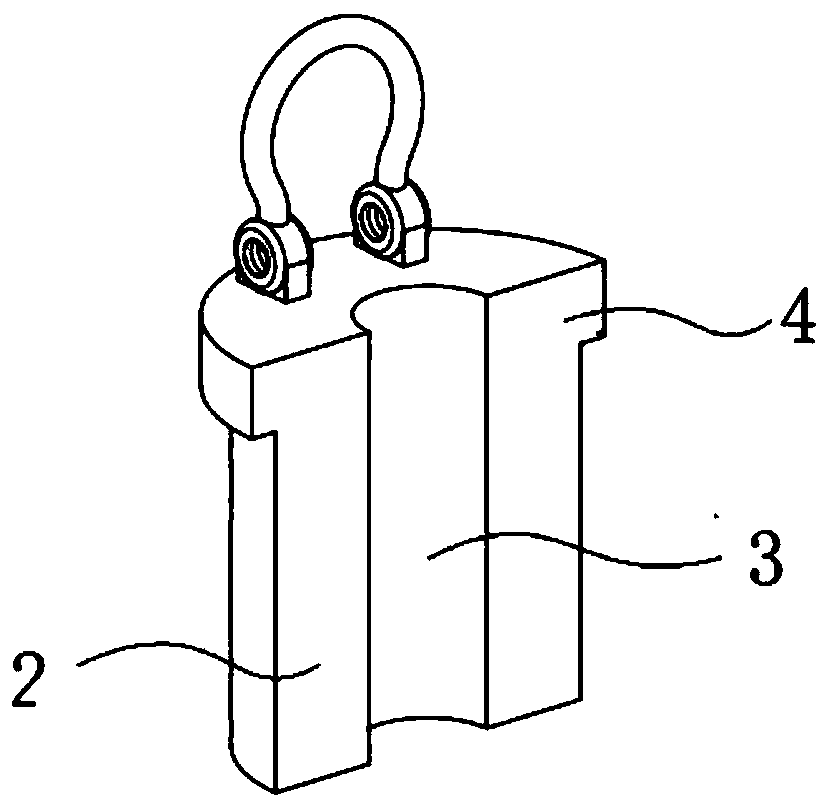
[0032]Embodiment 1 A probe rod guiding device for cone dynamic penetration test and standard penetration test, comprising two oppositely placed guiding cylindrical blocks 2, and a concave cylindrical guiding block is provided in the middle of the guiding cylindrical block Groove 3, the outer diameter of the straightening cylindrical block is adapted to the inner diameter of the drill groove drilled by the drilling machine, so that the two straightening cylindrical blocks are fitted and installed in the drilling groove 6 after being joined, and the straightening cylindrical block The upper outer edge of the block is provided with a flange segment 4 whose outer diameter is not smaller than the inner diameter of the outer drilling groove. When in use, the two halves of the oppositely placed guide cylinder block 2 are clamped on the shaft body of the conical power penetrator, and then placed into the drill groove 6. The outer wall of the guide cylinder block 2 and the inner wall of...
Embodiment 2
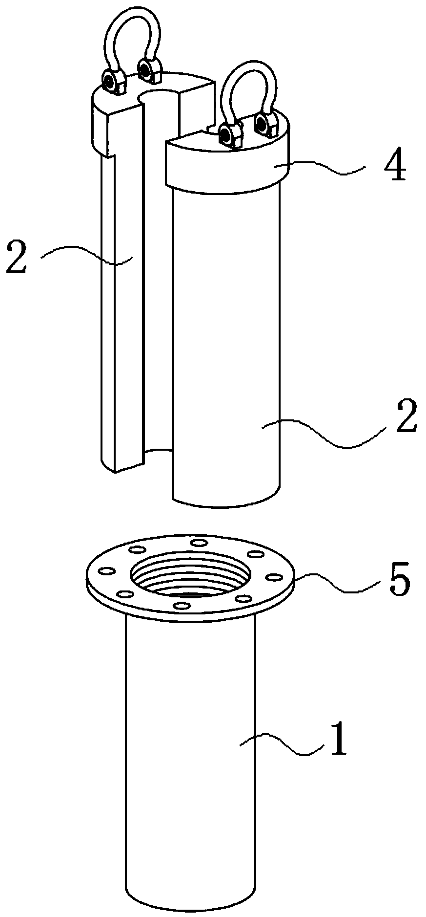
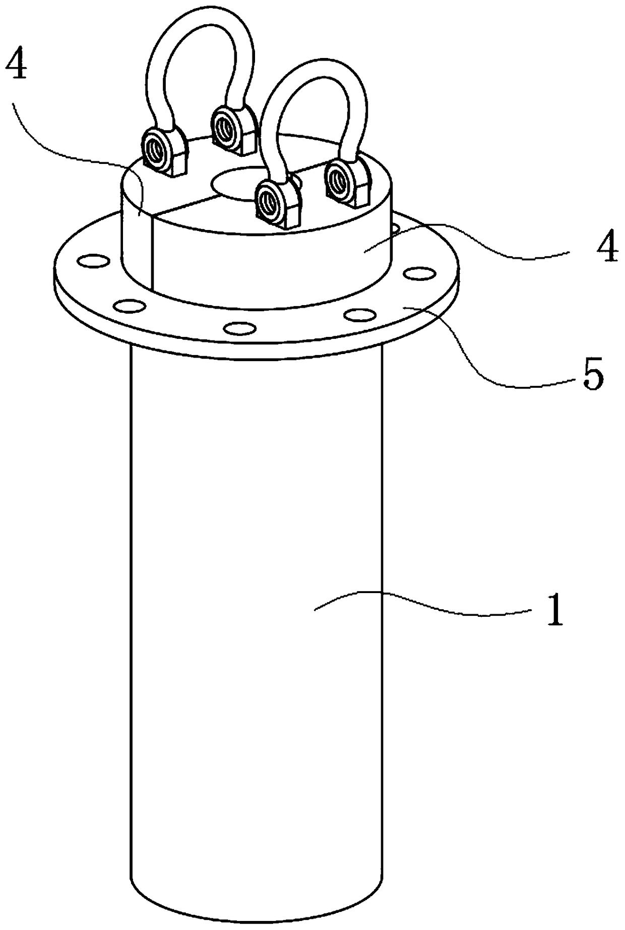
[0033] Embodiment 2: as Figure 1~5 As shown in the figure, a probe rod guiding device for cone dynamic penetration test and standard penetration test includes an outer sleeve 1 and two semi-opposite guiding cylindrical blocks 2, and the middle part of the guiding cylindrical block 2 is provided with Concave cylindrical alignment groove 3, the outer diameter of the alignment cylindrical block 2 is adapted to the inner diameter of the outer sleeve 1, so that the two alignment cylindrical blocks 2 are fitted and installed in the outer sleeve 1 after being joined , the upper outer edge of the straightening cylindrical block 2 is provided with a flange section 4 with an outer diameter not smaller than the inner diameter of the outer sleeve 1, and a flange connection plate 5 is installed on the outer edge of the upper port of the outer sleeve 1. The inner diameter of the cylindrical guiding groove 3 is 1-2 mm larger than the outer diameter of the probe rod 18, and the outer diamete...
Embodiment 3
[0036] Embodiment 3: as Figure 6 As shown, on the basis of Embodiment 1, two semi-opposite guiding upper column blocks 7 are connected above the flange land 5, and the bottom edge of the guiding upper column block 7 is provided with a The connecting plate 5 is connected to the flange connecting plate 5 through a number of first bolt holes installed in abutting connection with the flange connecting plate 5, and the bottom of the upper column block 7 is provided with a fixed ring 9 extending parallel to the outside. The fixed ring 9 is fixed by several second bolts 10 and passed through the fixed ring 9 and the flanged plate 5 in turn, and finally installed on the support frame 11 at the bottom of the drilling machine 19, the outer diameter of the upper column block 7 is larger than the On the outer diameter of the outer sleeve 1 , the middle part of the inner surface of the upper alignment column 7 is provided with an alignment groove 12 consistent with the cylindrical alignme...
PUM
 Abstract
Description
Claims
Application Information
 - R&D
- Intellectual Property
- Life Sciences
- Materials
- Tech Scout
- Unparalleled Data Quality
- Higher Quality Content
- 60% Fewer Hallucinations
Browse by: Latest US Patents, China's latest patents, Technical Efficacy Thesaurus, Application Domain, Technology Topic, Popular Technical Reports.
© 2025 PatSnap. All rights reserved.Legal|Privacy policy|Modern Slavery Act Transparency Statement|Sitemap|About US| Contact US: help@patsnap.com


