Autonomous obstacle avoidance method for unmanned boat integrating radar and photoelectric information

An unmanned boat, optoelectronic technology, applied in the reflection/re-radiation of radio waves, non-electric variable control, radio wave measurement system, etc. Safe, effective autonomous obstacle avoidance, and the effect of improving the degree of intelligence

Active Publication Date: 2019-02-01
中船鹏力(南京)大气海洋信息系统有限公司 +1
View PDF34 Cites 18 Cited by
  • Summary
  • Abstract
  • Description
  • Claims
  • Application Information

AI Technical Summary

Problems solved by technology

[0004] 1. The perception source of surface targets often comes from a single detection method, such as radar, photoelectricity, AIS, etc., which often results in a high false alarm rate in target detection or the inability to accurately and comprehensively grasp target motion information, target outline, etc., so it cannot provide obstacle avoidance. source of accurate information
[0005] 2. In the traditional obstacle avoidance process, simply following the Maritime Collision Avoidance Convention, it is impossible to quantify the change in the speed and course of the unmanned vessel, which often results in a large amount of change, resulting in a large amount of path waste and energy consumption of the unmanned vessel itself. Or the amount of change is small and the obstacle avoidance cannot be successful, or when the obstacle avoidance is too close to the target, it is affected by the eddy current generated by it, causing serious accidents.

Method used


Image

  • Autonomous obstacle avoidance method for unmanned boat integrating radar and photoelectric information
  • Autonomous obstacle avoidance method for unmanned boat integrating radar and photoelectric information
  • Autonomous obstacle avoidance method for unmanned boat integrating radar and photoelectric information

Examples


Embodiment Construction

[0037] The present invention will be further described in detail below in conjunction with the accompanying drawings and specific preferred embodiments.

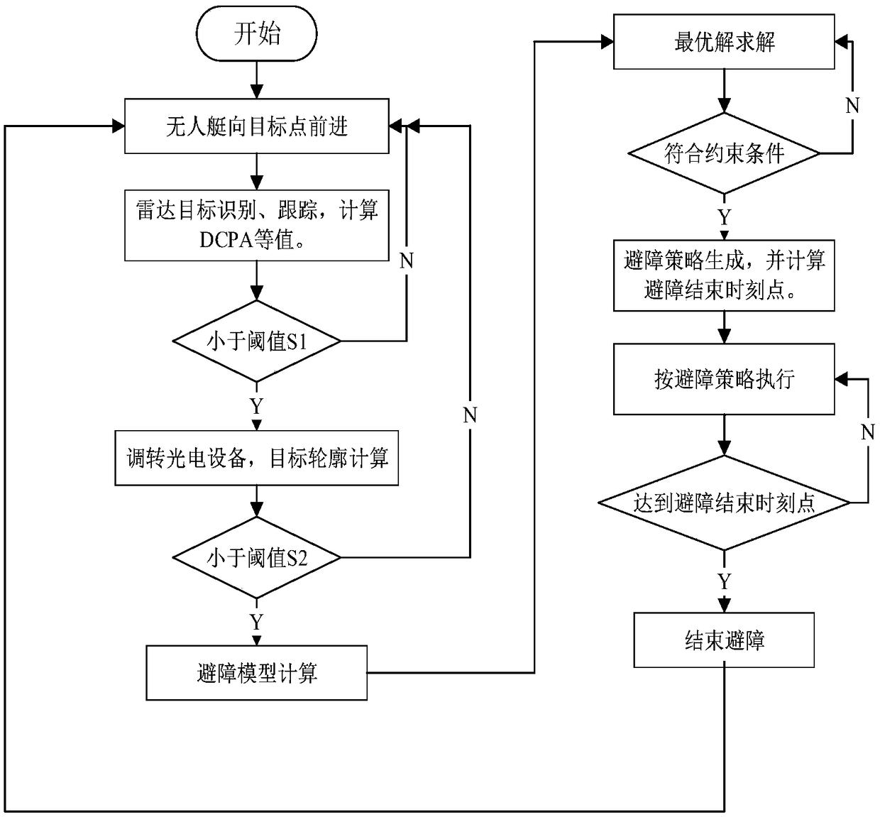
[0038] Such as figure 1 As shown, an autonomous obstacle avoidance method for unmanned boats that fuses radar and photoelectric information includes the following steps.

[0039]Step 1: Initial judgment of obstacle targets: The navigation radar on the unmanned boat is used to identify and track the obstacle targets entering its range, and the detection range is set to 500m. DCPA1 is calculated separately through radar echoes and auxiliary navigation information (including navigation information of GPS, compass and other equipment). Among them, DCPA1 represents the minimum encounter distance value between each obstacle target and the UAV. Then, compare and judge the DCPA1 value with the set threshold S1; wherein, the set threshold S1 is 5 to 10 times the length of the unmanned boat, preferably 50 m.

[0040] At the same ti...


PUM


Abstract

The invention discloses an autonomous obstacle avoidance method for an unmanned boat integrating radar and photoelectric information; the method mainly comprises the following steps of performing obstacle target primary judgment, obstacle target maximum length value calculation, obstacle target secondary judgment, obstacle avoidance model determination, speed and course change quantity optimal solution acquisition, obstacle avoidance ending point determination and the like. According to the method, the radar and the photoelectric equipment are combined to accurately obtain the motion information and the outline information of the obstacle target, and the obstacle avoidance model capable of quantizing the speed and course change quantity of the unmanned boat is given, and then the optimal solution meeting a plurality of conditions including a maritime obstacle avoidance rule is obtained through a particle swarm algorithm; finally, the obstacle avoidance ending time point is determined,and a route is re-planned to move forward to the previous target. According to the method, the obstacle avoidance can be rapidly and safely realized, the running path cannot be wasted, and the intelligent degree of the unmanned boat is improved, and the method can be widely applied to the field of intelligent navigation of military or civilian unmanned boats at the later stage, so that the navigation safety of the unmanned intelligent aircraft in a complex water area is improved.

Description

technical field [0001] The invention relates to the technical field of intelligent navigation of unmanned boats, in particular to an autonomous obstacle avoidance method for unmanned boats that integrates radar and photoelectric information. Background technique [0002] As an unmanned surface platform, unmanned boats can expand the existing combat capabilities in the military. Intelligent unmanned boats with search and attack functions and can be configured according to tasks can quickly make up for our army's asymmetric combat capabilities at a relatively low cost. The deficiencies in the system are of great significance to improving our military's maritime combat capabilities. In terms of civilian use, unmanned boats have important application value in patrolling, monitoring, disaster warning and disaster relief under complex and dangerous sea conditions such as oceans and large lakes. There are often many surface targets in the waters where unmanned boats travel, such a...

Claims


Application Information

Patent Timeline
Patent Type & Authority Applications(China)
IPC IPC(8): G05D1/02G01S13/93G01S13/86
CPCG01S13/86G05D1/0231G05D1/0257G01S13/937
Inventor 叶楠徐坤宗成明李凯金家龙王祥
Owner 中船鹏力(南京)大气海洋信息系统有限公司
Why Eureka
Try Eureka