Error correction method used for improving data error correction efficiency under high error rate environment

An error correction method and bit error rate technology, applied in the field of error correction of data error correction efficiency, can solve problems such as inability to transmit, reduce effective data ratio, error retransmission, etc., and achieve the effect of improving data error correction efficiency

Inactive Publication Date: 2019-02-01
SHENZHEN ELINK SMART CO LTD
View PDF6 Cites 6 Cited by
  • Summary
  • Abstract
  • Description
  • Claims
  • Application Information

AI Technical Summary

Problems solved by technology

[0002] Wireless transmission technology is widely used in distributed security monitoring, traffic monitoring, industrial monitoring, home monitoring and many other fields. The wireless transmission widely used in the smart home field includes 433, zigbee, Bluetooth, and WIFI. However, in the specific use process, wireless The signal becomes worse with the increase of the transmission distance, and there will be bit errors in the transmission. When the bit error rate is high to a certain extent, the transmission speed will be slow or even impossible to transmit. Error retransmission: When the receiving end detects a data transmission error, it will feedback and resend ;Redundant error correction code: By adding redundant error correction codes after transmitting data, the receiving end automatically corrects errors; during operation, error retransmission will consume a lot of time on retransmission, resulting in a decrease in transmission speed. If the bit error rate is higher than a certain value (above 1%), there will be a bit error in each transmission, and the transmission will not be possible. The additional redundant information added in the redundant error correction code will reduce the effective data ratio, reduce the transmission speed, and redundant The remaining error correction capability is limited. If the number of errors exceeds the error correction capability, error correction will not be possible

Method used


Image

  • Error correction method used for improving data error correction efficiency under high error rate environment

Examples


Embodiment Construction

[0017] In order to make the object, technical solution and advantages of the present invention clearer, the present invention will be further described in detail below in conjunction with the accompanying drawings and embodiments. It should be understood that the specific embodiments described here are only used to explain the present invention, not to limit the present invention.

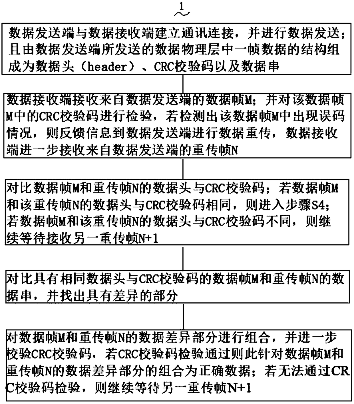
[0018] see figure 1 , an error correction method 1 for improving data error correction efficiency in a high bit error rate environment of the present invention comprises the following steps,

[0019] S1: The data sending end establishes a communication connection with the data receiving end, and sends data; and the structure of a frame of data in the data physical layer sent by the data sending end is composed of a data header (header), CRC check code and data string ;

[0020] S2: The data receiving end receives the data frame M from the data sending end; and checks the CRC check code in the dat...


PUM


Abstract

The invention provides an error correction method used for improving the data error correction efficiency under a high error rate environment. The method comprises the steps as follows: S1, a data sending end builds a communication connection with a data receiving end; and the structure of a frame of data in a data physical layer sent by the data sending end is formed into a header, a CRC check code and a data sting; and S2, a data receiving end receives a data frame M from the data sending end; the CRC check code in the data frame M is checked, if the condition that an error code occurs in the data frame M is detected, information is fed back to the data sending end to perform data retransmission, the data receiving end further receives a retransmission frame N from the data sending end;during an actual application process, if the CRC check code passes the check, the combination of data difference parts of the data frame M and the retransmission frame N is correct data, if the CRC check code cannot pass the check, the other retransmission frame N+1 is waited continuously; according to data error correction in such mode, the data error correction efficiency under the high error rate environment can be significantly improved.

Description

[technical field] [0001] The invention relates to the technical field of data error correction methods, in particular to an error correction method for improving data error correction efficiency in a high bit error rate environment with high data transmission rate and outstanding error correction rate. [Background technique] [0002] Wireless transmission technology is widely used in distributed security monitoring, traffic monitoring, industrial monitoring, home monitoring and many other fields. The wireless transmission widely used in the smart home field includes 433, zigbee, Bluetooth, and WIFI. However, in the specific use process, wireless The signal becomes worse with the increase of the transmission distance, and there will be bit errors in the transmission. When the bit error rate is high to a certain extent, the transmission speed will be slow or even impossible to transmit. Error retransmission: When the receiving end detects a data transmission error, it will feed...

Claims


Application Information

Patent Timeline
Patent Type & Authority Applications(China)
IPC IPC(8): H04L29/06H04L29/08H04L1/00
CPCH04L1/0061H04L67/141H04L69/06H04L69/22
Inventor 柯浩伟郭俊峰
Owner SHENZHEN ELINK SMART CO LTD
Why Eureka
Try Eureka