Heliostat Correction System Based on Celestial Body Images and Its Method

a technology of celestial body and correction system, applied in the field of heliostat correction, can solve the problems of affecting power generation efficiency, affecting the efficiency of power generation, and the number of heliostats that can be corrected at the same time, and the method with low efficiency usually takes a long time to make the heliostat. , to achieve the effect of ensuring the efficiency of heliostat correction, reducing the possibility of error, and low difficulty

Active Publication Date: 2019-05-30
SHANGHAI PARASOL RENEWABLE ENERGY CO LTD
View PDF0 Cites 7 Cited by
  • Summary
  • Abstract
  • Description
  • Claims
  • Application Information

AI Technical Summary

Benefits of technology

[0034]1. The present invention takes celestial bodies (such as the sun, the moon, first-class stars, etc.) that move regularly and have a certain brightness as markers, and can carry out correction during the day and at night, thus reducing the influence on the power generation efficiency and improving the correction efficiency.
[0035]2. The present invention takes celestial bodies that move regularly and have a certain brightness as markers, aligns the surface normal of the heliostat with the center of the celestial body, and then calculates the included angle between the surface normal vector and the incident vector through the image acquisition module, and calculates the deviation of the mechanical motion of the heliostat, so that all the heliostats to be corrected can be corrected simultaneously and concurrently by an independent heliostat correction system, thus greatly improving the correction efficiency.
[0036]3. A single heliostat correction system is only responsible for the correction of one heliostat and the correction systems on different heliostats are independent of each other. Therefore, failure of a certain heliostat correction system will only affect the heliostat to which it belongs and will not affect the heliostat correction progress of the solar thermal power station.
[0037]4. The heliostat correction system comprises an image acquisition module, a data analysis module, a correction calculation module, a data storage module and a communication module. A single heliostat correction system can independently complete all the correction work of a single heliostat, and can ensure the efficiency of heliostat correction.
[0038]5. The communication module can send the updated single correction period control command list to the heliostat without sending the data back to the upper computer for processing and then sending by the upper computer, thus reducing the possibility of error.
[0039]6. The heliostat correction system can be directly installed on the reflecting surface of the heliostat, and the modularized heliostat correction system can be replaced directly in case of failure, so the equipment maintenance is of low difficulty and cost.

Problems solved by technology

Although sufficient mechanical motion accuracy of the heliostat has been ensured in design, various new errors will be introduced in the process of processing, manufacturing, transportation and installation as well as daily operation, such as tilt of the rotation axis of the heliostat, foundation deformation, installation attitude deviation, deformation of the supporting structure, etc., making the newly installed heliostat unable to meet the design requirements and its reflected spot position will shift, thus directly affecting the power generation efficiency.
Although the above three methods are all traditional methods of heliostat correction, the number of heliostats that can be corrected at the same time is limited because the light spot carriers (white boards, photosensitive arrays, image acquisition devices, etc.) they use are installed on the tower.
Obviously, the traditional correction methods with low efficiency usually take a long time to make the heliostats in the whole solar thermal power station reach the optimal working state, which can no longer meet the operational requirements of modern solar thermal power stations.

Method used


Image

  • Heliostat Correction System Based on Celestial Body Images and Its Method
  • Heliostat Correction System Based on Celestial Body Images and Its Method
  • Heliostat Correction System Based on Celestial Body Images and Its Method

Examples


Embodiment Construction

[0048]The present invention will now be described in detail with reference to the accompanying drawings and embodiments.

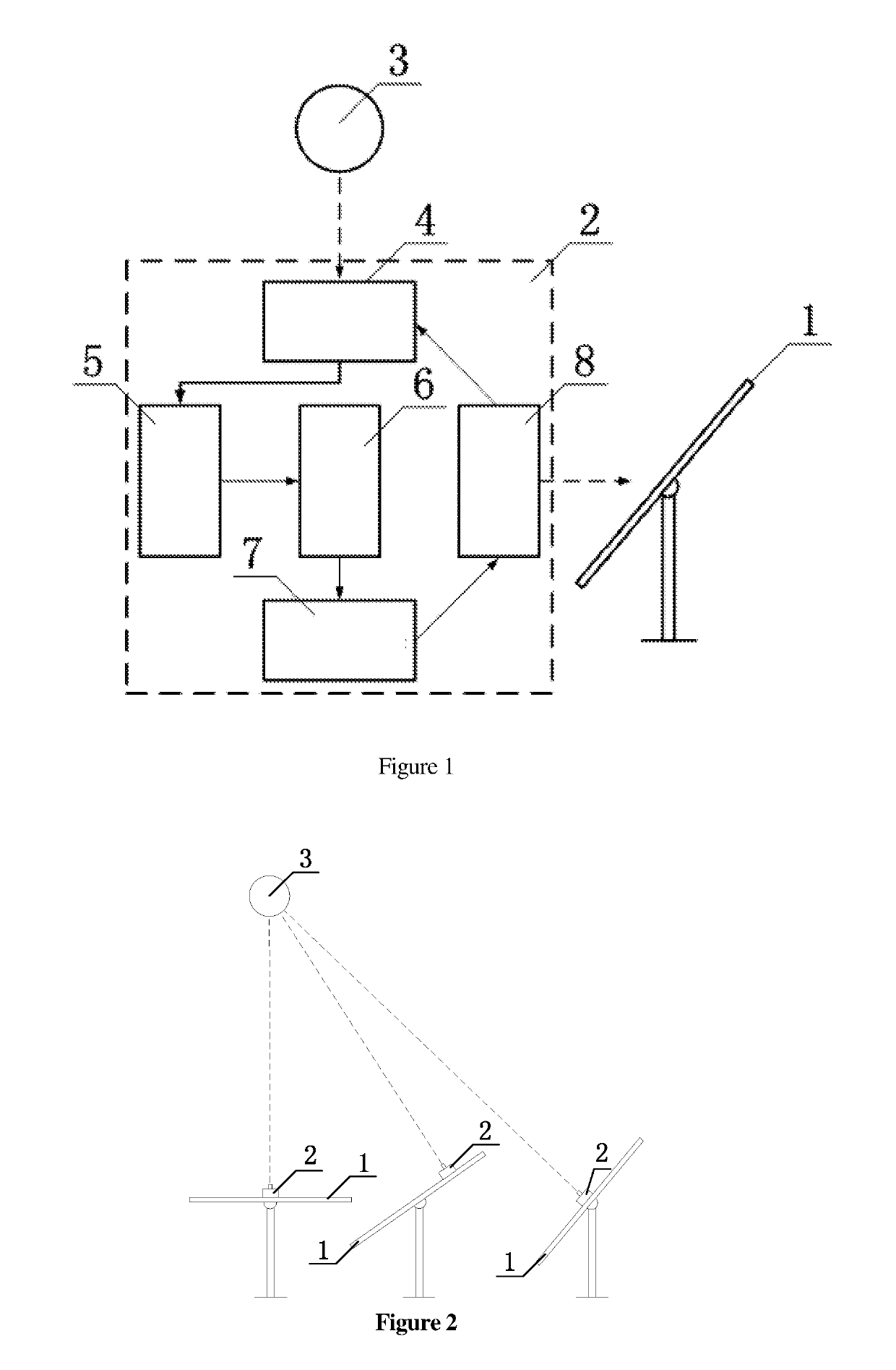
[0049]As shown in FIGS. 1 to 7, a heliostat correction system based on celestial body images comprising a heliostat 1 which is fixed on the rotation axis; the reflecting surface of the heliostat 1 is provided with a heliostat correction system 2; in the present invention, the heliostat correction system 2 comprises an image acquisition module 4, a data analysis module 5, a correction calculation module 6, a data storage module 7 and a communication module 8, and is used for the daily correction of the heliostat 1 in the solar thermal power station. The image acquisition module 4 comprises a light intensity adjusting device (a neutral attenuation sheet or other device capable of adjusting the incident light intensity of a celestial body), an imaging light path (a lens or a pinhole) and a digital image sensor; the image acquisition module 4 is in the same direction a...


PUM


Abstract

A heliostat correction system includes an image acquisition module for acquiring the image of a celestial body in a field of view and sending the image to a data analysis module which analyzes the deviation value between the celestial body image and the image center in an image coordinate system and transmits the deviation value to a correction calculation module which decomposes the deviation to a corresponding rotation axis according to the rotation mode of a heliostat to obtain the deviation angle of each rotation axis; a data storage module is used to store the correction result of the heliostat and the single correction period control command list of the heliostat; a communication module reads the single correction period control command list from the data storage module, sends the list to the heliostat, and simultaneously controls the image acquisition module to shoot according to the rotation period of the heliostat.

Description

CROSS REFERENCE TO RELATED APPLICATIONS[0001]The present application is a Continuation-In-Part application of PCT Application No. PCT / CN2018 / 081854 filed on Apr. 4, 2018, which claims the benefit of Chinese Patent Application No. 201711209150.3 filed on Nov. 27, 2017. All the above are hereby incorporated by reference.FIELD OF THE INVENTION[0002]The present invention relates to a heliostat correction system based on celestial body images and its method, and belongs to the technical field of heliostat correction.BACKGROUND OF THE INVENTION[0003]In a solar thermal power station, a certain number of heliostats are used to reflect the sunlight in an area into a heat absorber area, and the energy required for power generation is obtained by concentrating the sunlight. However, the position of the sun changes continuously with time, so the heliostats need to move continuously to correct the exit direction of the reflected light, so that the light spot can accurately fall in the area of th...

Claims


Application Information

Patent Timeline
Patent Type & Authority Applications(United States)
IPC IPC(8): F24S50/20F24S20/20G05B23/02G05D3/12G06K9/20G06V10/147
CPCF24S50/20F24S20/20G05B23/02G05D3/12G06K9/209G06T7/30G06T7/70G05B13/042G05D3/105Y02E10/47F24S80/00F24S23/70G06V10/245G06V10/147G05B19/402
Inventor SUN, NANSHEN, PINGYOU, SILIANGCHEN, YUDA
Owner SHANGHAI PARASOL RENEWABLE ENERGY CO LTD
Why Eureka
Try Eureka