Backlight source optical film dust removal device

A dust removal device and optical film technology, applied in chemical instruments and methods, cleaning methods and utensils, cleaning methods using gas flow, etc., can solve the problem that the optical film is easy to be stained with dust, has no device structure, and does not specify the specific structure of the dust removal device, etc. question

Inactive Publication Date: 2019-02-05
YANCHENG SANDING ELECTRONICS TECH CO LTD
View PDF7 Cites 3 Cited by
  • Summary
  • Abstract
  • Description
  • Claims
  • Application Information

AI Technical Summary

Problems solved by technology

[0003] During the production process, the optical film is easily contaminated with dust. Dust sticking to the optical film will have a great impact on the backlight source. Both the front and back of the optical film are easily stained with dust.
The patent No. CN 1854020 A proposes an automatic processing method for optical film plates before packaging. There is no specific device structure in this method, nor does it point out the specific structure of the dust removal device. Therefore, the present invention proposes a backlight optical Membrane dust removal device to solve the above problems

Method used


Image

  • Backlight source optical film dust removal device
  • Backlight source optical film dust removal device
  • Backlight source optical film dust removal device

Examples


Embodiment Construction

[0019] The following will clearly and completely describe the technical solutions in the embodiments of the present invention with reference to the accompanying drawings in the embodiments of the present invention. Obviously, the described embodiments are only some, not all, embodiments of the present invention.

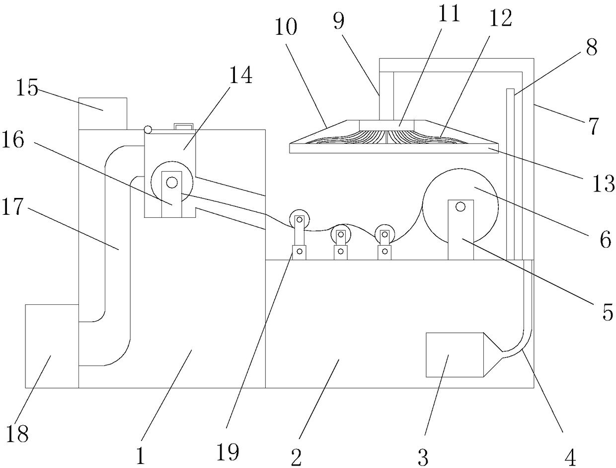
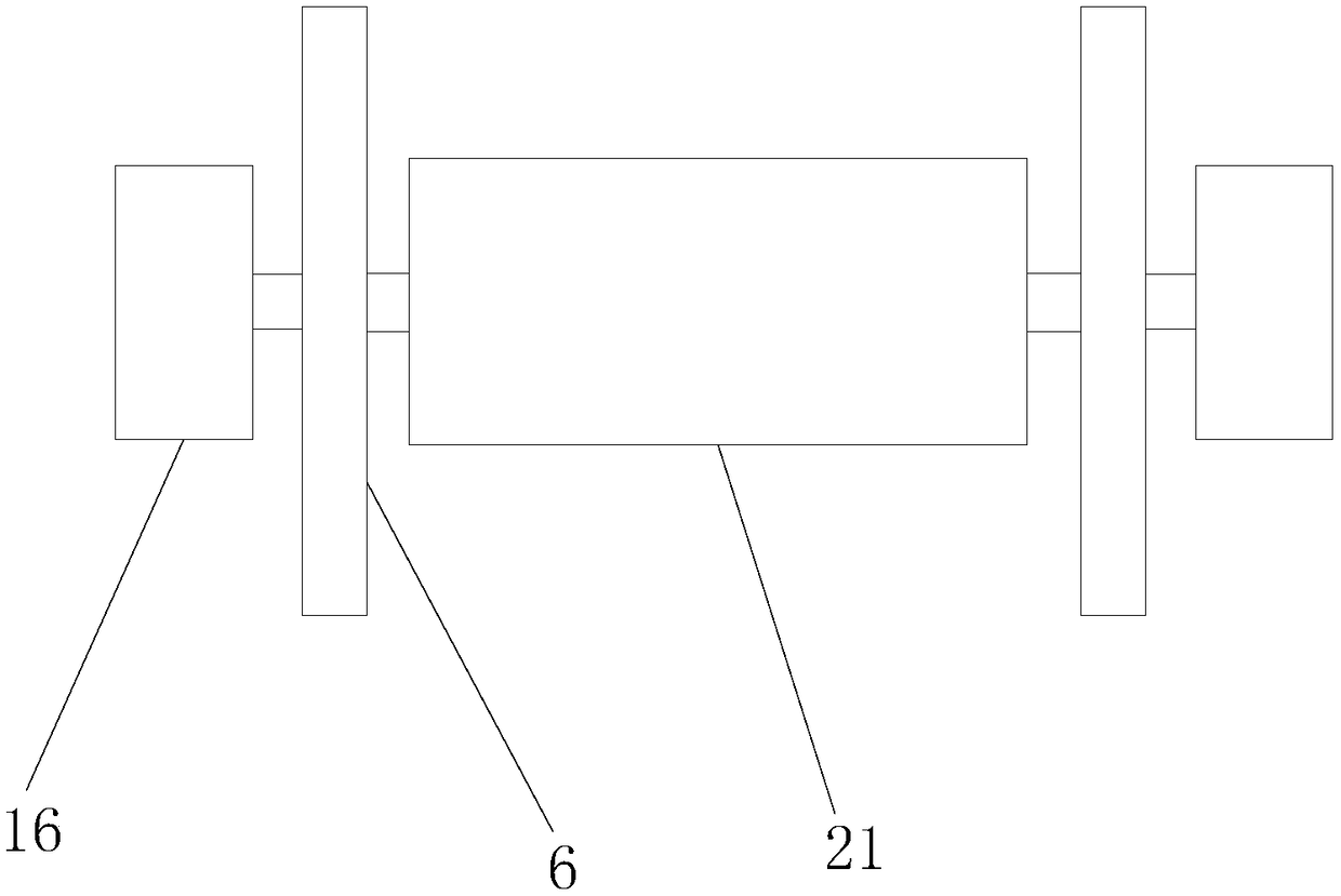
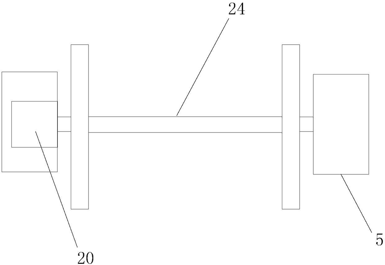
[0020] refer to Figure 1-4 , a backlight optical film dust removal device, comprising a box 1 and a workbench 2, the box 1 is adjacent to the workbench 2, and the height of the workbench 2 is 1 / 2 of the box 1, the box 1 is provided with a controller 15, the top of the box 1 is provided with a groove 14, the bottom of the groove 14 is equipped with an optical film release device, the optical film release device includes a pair of support seats 16, a roller 21 and A pair of circular plates 6, wherein a rotating shaft is welded between a pair of supporting seats 16, and a roller 21 is slidably connected to the middle of the rotating shaft, and a circular plate 6 is fix...


PUM


Abstract

The invention discloses a backlight source optical film dust removal device. The backlight source optical film dust removal device comprises a box body and a workbench, wherein the box body is adjacent to the workbench, the height of the workbench is one half of the box body, a controller is arranged at the top of the box body, and an optical film releasing device is arranged at the bottom of a groove; the optical film releasing device comprises a pair of supporting seats, a roller and a pair of round plates, a rotating shaft is arranged in an open hole, a dust removal rubber roller is arranged on the rotary shaft, bearings are arranged at the two ends of the dust removal rubber roller, the side face of the workbench is provided with a second air suction fan, the air suction end of the second air suction fan is connected with a second pipeline, a connecting rod is welded at the tail end of an L-shaped supporting rod, the lower end of the connecting rod is fixedly provided with an air suction device, and the air suction device is located right above the workbench. According to the backlight source optical film dust removal device, the design of the first air suction fan, dust suction treatment can be carried out on the periphery of the optical film releasing device in the box body, and dust on the periphery of the optical film releasing device is prevented from polluting the secondary dust of an optical film.

Description

technical field [0001] The invention relates to the technical field of dust removal devices, in particular to a backlight optical film dust removal device. Background technique [0002] Backlight (BackLight) is a light source located behind the liquid crystal display (LCD), and its luminous effect will directly affect the visual effect of the liquid crystal display module (LCM). The LCD itself does not emit light, it displays graphics or the result of its modulation of light. The backlight is mainly composed of a light source, a light guide plate, an optical module, and structural parts. The optical die includes an optical film, and the optical film includes a brightness enhancement film and a diffusion film. [0003] During the production process, the optical film is easily contaminated with dust. Dust sticking to the optical film will have a great impact on the backlight source, and the front and back of the optical film are easily stained with dust. The patent No. CN 1...

Claims


Application Information

Patent Timeline
Patent Type & Authority Applications(China)
IPC IPC(8): B08B7/00B08B5/04
CPCB08B5/04B08B7/0028
Inventor 赵圣铭
Owner YANCHENG SANDING ELECTRONICS TECH CO LTD
Why Eureka
Try Eureka