Welded combined T-shaped steel column correcting device and method

A technology of T-shaped steel and H-shaped steel, which is applied in the field of correcting devices for welded combined T-shaped steel columns, can solve the problems of no operating space, difficult correction, high energy consumption, etc., and achieve simple and safe operation, low manufacturing cost, and reduced labor intensity. Effect

Pending Publication Date: 2019-02-05
CHINA METALLURGICAL CONSTR ENG GRP
View PDF12 Cites 10 Cited by
  • Summary
  • Abstract
  • Description
  • Claims
  • Application Information

AI Technical Summary

Problems solved by technology

[0002] The welded combined T-shaped steel column is composed of welded H-shaped steel and welded T-shaped steel. The processing sequence is to process the welded H-shaped steel and welded T-shaped steel first, and use the flange straightener to straighten the welded H-shaped steel and welded T-shaped steel. The welded T-shaped steel is welded in the center of the web of the welded H-shaped steel. After welding, the two ends of the web centerline of the welded H-shaped steel will warp to the welding surface (ie, the direction of the T-shaped steel). Therefore, the welded H-shaped steel web after welding needs Correction, but this combination of steel columns is not easy to use existing equipment for correction
The traditional straightening method is to use a flame and a small jack to straighten manually. This method not only has low efficiency and high energy consumption, especially for composite steel columns with too thick plates and too narrow web and flange widths, the traditional straightening The method has no operation space

Method used


Image

  • Welded combined T-shaped steel column correcting device and method
  • Welded combined T-shaped steel column correcting device and method

Examples


Embodiment Construction

[0029] The present invention will be described in further detail below in conjunction with the accompanying drawings and specific embodiments.

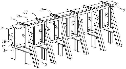
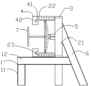
[0030] see figure 1 and figure 2 , a straightening device for welding combined T-shaped steel columns, the straightening device is composed of several straightening units and all the straightening units are arranged side by side on the same straight line, each straightening unit includes a platform support 1, two L-shaped clamps 4 and a jack 5, The platform support is welded into a "∏" shape by two columns 11 and a crossbeam 12, a vertical beam 21 perpendicular to the crossbeam 12 is arranged on the upper surface of the crossbeam 12, and two rectangular parallel to the crossbeam 12 are arranged at the two ends of the vertical beam 21. Connecting block 22, the distance between the two connecting blocks 22 is equal to the sum of the width of the welded H-shaped steel web and the thickness of the two flanges of the welded combined T-sh...


PUM


Abstract

The invention discloses a welded combined T-shaped steel column correcting device and method. The correcting device is composed of multiple correcting units which are on the same straight line. Each correcting unit comprises a platform support, two L-shaped clamps and a jack. Each platform support is formed by welding two stand columns and a cross beam. A vertical beam is arranged on the upper surface of each cross beam, wherein each vertical beam is perpendicular to the corresponding cross beam. The two ends of each vertical beam are provided with two rectangular connecting blocks, wherein every two rectangular connecting blocks are parallel with the corresponding cross beam. Each connecting block is uniformly provided with multiple threaded holes. Each L-shaped clamp is integrally formedby a transverse plate and a vertical plate. Each transverse plate is provided with threaded holes matched with the threaded holes in the connecting blocks. Threaded connecting pieces penetrate the threaded holes in the transverse plates and the threaded holes in the connecting blocks, so that the two L-shaped clamps are fixedly connected with the two connecting blocks correspondingly. Each jack is arranged between the corresponding vertical beam and a to-be-corrected welded H-shaped profile steel web plate. A base of each jack tightly jacks the corresponding vertical beam. The stroke end of each jack tightly jacks the corresponding to-be-corrected welded H-shaped profile steel web plate. The welded combined T-shaped steel column correcting device has the advantages of being simple in structure, easy to operate, low in cost, high in efficiency and the like.

Description

technical field [0001] The invention belongs to the technical field of building steel structures, and in particular relates to a straightening device and a straightening method for a welded combined T-shaped steel column. Background technique [0002] The welded combined T-shaped steel column is composed of welded H-shaped steel and welded T-shaped steel. The processing sequence is to process the welded H-shaped steel and welded T-shaped steel first, and use the flange straightener to straighten the welded H-shaped steel and welded T-shaped steel. The welded T-shaped steel is welded in the center of the web of the welded H-shaped steel. After welding, the two ends of the web centerline of the welded H-shaped steel will warp to the welding surface (ie, the direction of the T-shaped steel). Therefore, the welded H-shaped steel web after welding needs Correction, but this combination of steel columns is not easy to use existing equipment for correction. The traditional straigh...

Claims


Application Information

Patent Timeline
Patent Type & Authority Applications(China)
IPC IPC(8): B21D3/10
CPCB21D3/10
Inventor 刘金芳徐国友宋林周敬张望
Owner CHINA METALLURGICAL CONSTR ENG GRP
Why Eureka
Try Eureka