Dynamic balance ring and design method thereof

A ring body and ring width technology, applied in the field of dynamic balance ring and its design, can solve problems such as unbalanced rotation, and achieve the effect of reducing mechanical failures

Pending Publication Date: 2019-02-05
CONPROFE TECH GRP CO LTD +1
View PDF8 Cites 0 Cited by
  • Summary
  • Abstract
  • Description
  • Claims
  • Application Information

AI Technical Summary

Problems solved by technology

[0003] The purpose of the present invention is to provide a dynamic balance ring and its design method to solve the problem in the prior art that the center of gravity of the tool handle and the cutter head changes, and the rotation will occur during the rotation of the tool handle and the cutter head. unbalanced technical issues

Method used


Image

  • Dynamic balance ring and design method thereof
  • Dynamic balance ring and design method thereof
  • Dynamic balance ring and design method thereof

Examples


Embodiment 1

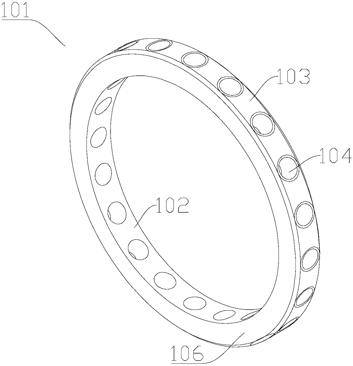
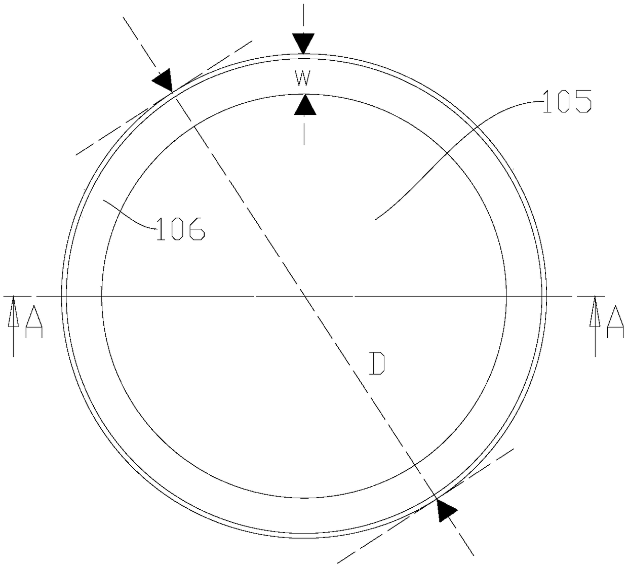
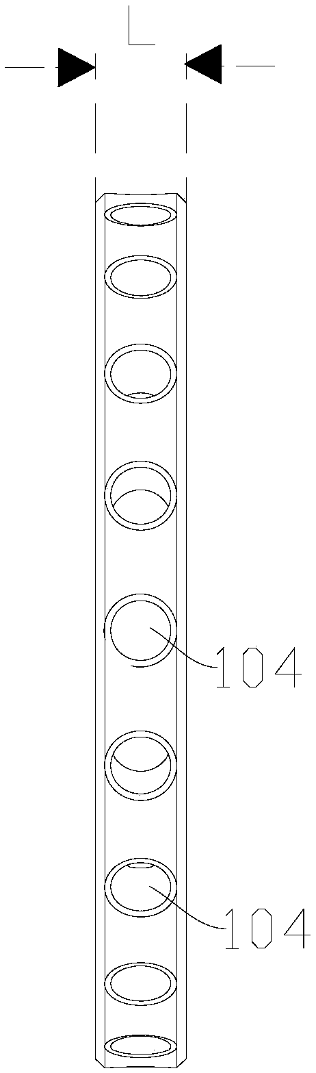
[0044] figure 1 It is a schematic diagram of the structure of the ring body in Example 1 of the present invention; figure 2 It is the front view of the ring body in Embodiment 1 of the present invention; image 3 It is the right side view of the ring body in Embodiment 1 of the present invention; Figure 4 for figure 2 A sectional view along line A-A; Figure 5 It is a structural schematic diagram of the adjusting device in Embodiment 1 of the present invention; see Figure 1 to Figure 5 As shown, Embodiment 1 of the present invention provides a dynamic balance ring, the dynamic balance ring includes a ring body 101, the ring body 101 has an opposite inner surface 102 and an outer surface 103, and the inner surface 102 is used to enclose the ring body 101 The mounting hole 105 in the middle; the outer surface 103 is provided with a plurality of counterweight holes 104, and the plurality of counterweight holes 104 are arranged along the length direction of the outer surfa...

Embodiment 2

[0068] The dynamic balance ring in the second embodiment is an improvement on the basis of the first embodiment. The technical content disclosed in the first embodiment will not be described repeatedly, and the content disclosed in the first embodiment also belongs to the content disclosed in this embodiment.

[0069] In the optional solution of this embodiment, the aperture of the counterweight hole 104 is linearly related to the outer diameter of the ring body 101, the axial length of the ring body 101, and the ring width of the ring body 101. Through experimental calculation, when the linear correlation is made, it is convenient Equipped with corresponding adjustment devices, it is beneficial to quickly adjust the balance.

[0070] Specifically, the diameter of the counterweight hole 104 satisfies the following formula:

[0071] d=xD+yL+zW+C,

[0072] Among them, d represents the aperture diameter of the counterweight hole 104 (both the hole diameter of the counterweight h...


PUM


Abstract

The invention relates to the technical field to ultrasonic machining, in particular to a dynamic balance ring and a design method of the dynamic balance ring. The dynamic balance ring comprises a ringbody, the ring body is provided with an inner side face and an outer side face which are opposite, an installation hole in the middle of the ring body is defined by the inner side face, the outer side face is provided with multiple balance weight holes, and the multiple balance weight holes are distributed in the length direction of the outer side face. After a knife handle and a knife disc are assembled into a whole, the dynamic balance ring is installed on a knife body of the knife handle or the knife disc, an object is installed in the balance weight hole in the dynamic balance ring, the space position of the gravity center of the whole formed by the knife handle, the knife disc and the dynamic balance ring is adjusted to be kept in the rotating axis of the knife handle, therefore, thebalance state in the rotating process can be maintained, and mechanical faults are reduced.

Description

technical field [0001] The invention relates to the technical field of ultrasonic processing, in particular to a dynamic balance ring and a design method thereof. Background technique [0002] Since the overall center of gravity formed by the tool handle and the cutter head changes, when the machine tool spindle drives the tool handle and the cutter head to move, there will be a phenomenon of unbalanced rotation, which is prone to mechanical failure. Contents of the invention [0003] The purpose of the present invention is to provide a dynamic balance ring and its design method to solve the problem in the prior art that the center of gravity of the tool handle and the cutter head changes, and the rotation will occur during the rotation of the tool handle and the cutter head. Unbalanced technical issues. [0004] The present invention provides a dynamic balance ring, comprising a ring body, the ring body has an inner side and an outer side opposite to each other, and the ...

Claims


Application Information

Patent Timeline
Patent Type & Authority Applications(China)
IPC IPC(8): B24B1/04B24B41/04
CPCB24B1/04B24B41/042
Inventor 颜炳姜李伟秋林一松
Owner CONPROFE TECH GRP CO LTD
Why Eureka
Try Eureka