Dynamic balance shank device

A dynamic balancing and tool holder technology, applied in positioning devices, devices for fixing grinding wheels, accessories of tool holders, etc., can solve problems such as rotational imbalance, and achieve the effects of ensuring machining accuracy, reducing mechanical failures and prolonging service life.

Pending Publication Date: 2018-12-07
CONPROFE TECH GRP CO LTD +1
View PDF8 Cites 0 Cited by
  • Summary
  • Abstract
  • Description
  • Claims
  • Application Information

AI Technical Summary

Problems solved by technology

[0004] The purpose of the present invention is to provide a dynamic balance tool handle device to solve the technical problem in the prior art that when the machine tool spindle drives the tool handle and the cutter head (or grinding head) to rotate, the phenomenon of unbalanced rotation is prone to occur

Method used


Image

  • Dynamic balance shank device
  • Dynamic balance shank device
  • Dynamic balance shank device

Examples


Embodiment 1

[0052] see Figure 1 to Figure 10 As shown, Embodiment 1 of the present invention provides a dynamic balance knife handle device, which includes a handle body 600 and a dynamic balance ring; the dynamic balance ring is installed on the handle body 600 .

[0053] The handle body 600 includes a main shaft installation part 601 and a balance ring installation part 602. The main shaft installation part 601 and the balance ring installation part 602 are connected.

[0054] One end of the spindle installation part 601 is used to connect with the machine tool spindle, the other end of the spindle installation part 601 is connected to one end of the balance ring installation part 602, and the other end of the balance ring installation part 602 is used to connect with the cutterhead or grinding head . The diameter of one end of the spindle mounting part 601 in the shape of a circular platform is smaller than the diameter of the other end, that is to say, one end of the balancing ring ...

Embodiment 2

[0078] see Figure 11 to Figure 19As shown, the second embodiment also provides a dynamic balance knife handle device. The dynamic balance knife handle device in this embodiment describes another implementation scheme in which the dynamic balance ring is installed on the handle body 600. In addition The technical solution of the first embodiment also belongs to this embodiment and will not be described again.

[0079] In this embodiment, the dynamic balance ring is installed on the handle body 600 through an ultrasonic transducer. There is no positioning boss in the first embodiment on the handle body.

[0080] In the optional solution of this embodiment, after the cylindrical boss 607 on the end surface of the other end of the balance ring installation part 602 in the first embodiment is omitted, an installation cavity is opened on the end surface of the other end of the balance ring installation part 602 , for installing the ultrasonic transducer; the installation cavity e...

Embodiment 3

[0103] The dynamic balancing knife handle device in the third embodiment is an improvement on the basis of the first or second embodiment, and the technical content disclosed in the first or second embodiment will not be described repeatedly. The disclosed content also belongs to the content disclosed in the third embodiment.

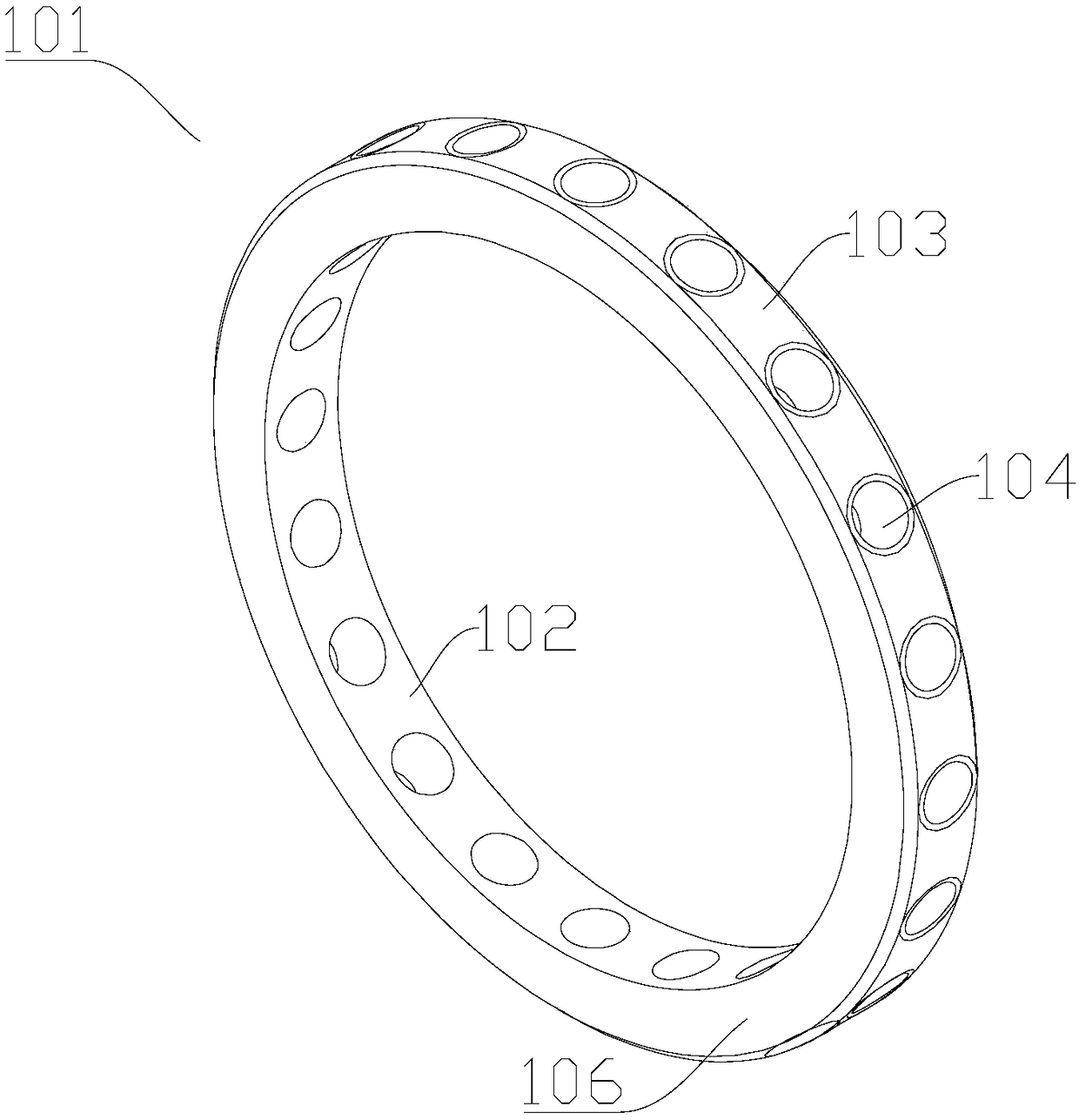
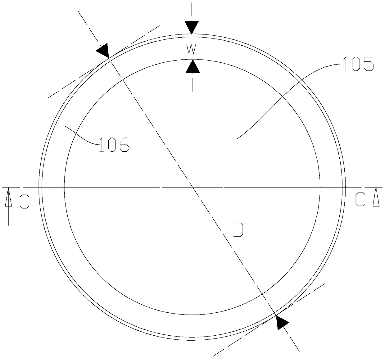
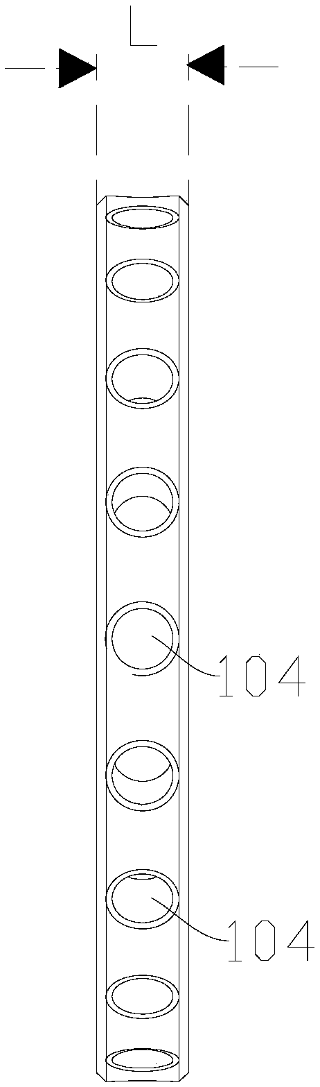
[0104] In this embodiment, the dynamic balance ring is mainly improved; the aperture of the counterweight hole 104 of the dynamic balance ring is linearly related to the outer diameter of the ring body 101, the axial length of the ring body 101 and the ring width of the ring body 101. It is estimated that when linearly related, it is convenient to configure the corresponding adjustment device, and it is beneficial to quickly adjust the balance.

[0105] Specifically, the diameter of the counterweight hole 104 satisfies the following formula:

[0106] d=xD+yL+zW+C,

[0107] Among them, d represents the aperture diameter of the counterweight hole 104 (b...


PUM


Abstract

The invention relates to the technical field of machining tool machining, in particular to a dynamic balance shank device. The dynamic balance shank device comprises a shank body and a dynamic balancering; the dynamic balance ring is mounted on the shank body; the shank body comprises a main shaft mounting part and a balance ring mounting part; the main shaft mounting part is connected with the balance ring mounting part; the main shaft mounting part is a round table; the balance ring mounting part is cylindrical; the dynamic balance ring comprises a ring body; the ring body is provided withan inner side surface and an outer side surface opposite to each other; the inner side surface is used for surrounding a mounting hole at the middle part of the ring body; the outer side surface is provided with multiple counterweight holes; and the multiple counterweight holes are distributed in the length direction of the outer side surface. The dynamic balance shank device facilitates maintenance of the balance state in the rotating process, reduces the mechanical faults, guarantees the machining precision, and prolongs the service life of a machining system.

Description

technical field [0001] The invention relates to the technical field of machine tool processing, in particular to a dynamic balancing tool handle device. Background technique [0002] TWM372763U discloses an ultrasonic vibration tool module, the first coil is fixed to the fixed body. The sound wave generator is electrically connected to the first coil. The rotating body is rotatably mounted to the fixed body. The second coil is fixed on the rotating body. The two first contacts are fixed on the rotating body and electrically connected to the second coil. The handle body is detachably mounted on the rotating body. The two second contacts are fixed on the knife handle body and electrically connected to the two first contacts respectively. The voltage stabilizing circuit board is arranged on the knife handle body, and has two input ends electrically connected to two second contact points for stabilizing the input voltage generated by the second coil when rotating and output...

Claims


Application Information

Patent Timeline
Patent Type & Authority Applications(China)
IPC IPC(8): B23B31/00B23Q3/12B23Q11/00B06B1/06B06B3/02B24B45/00
CPCB06B1/06B06B3/02B23B31/006B23Q3/12B23Q11/001B24B45/006
Inventor 颜炳姜李伟秋林一松
Owner CONPROFE TECH GRP CO LTD
Why Eureka
Try Eureka