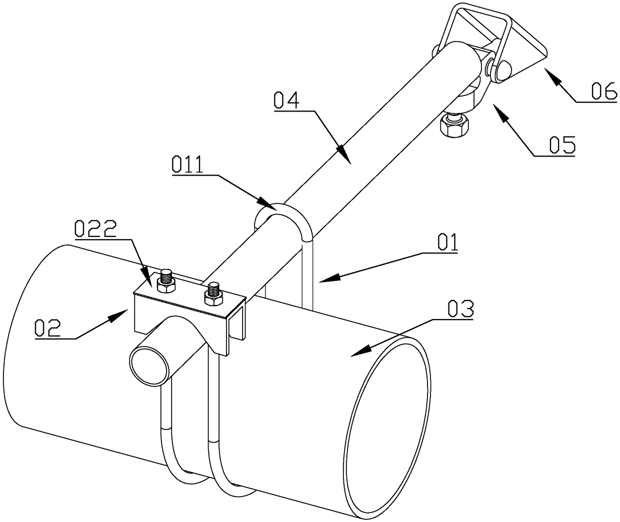
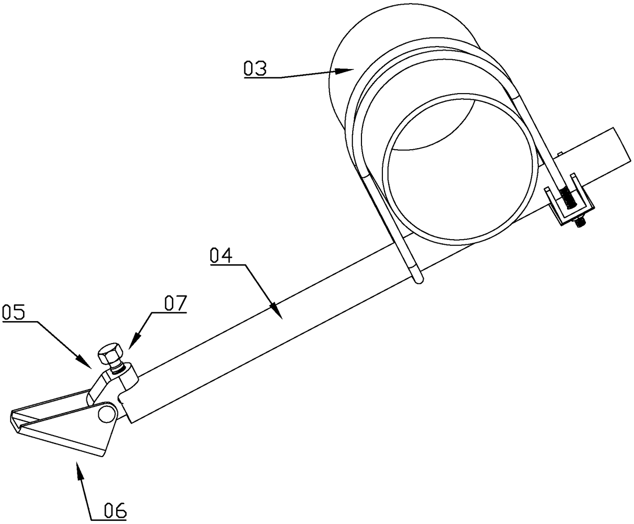
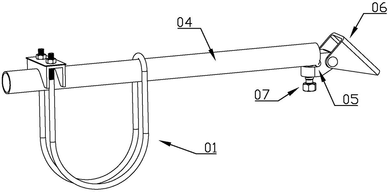
Building pipeline anti-knock device

A technology for anti-seismic devices and pipelines, which is applied in the direction of pipeline supports, pipes/pipe joints/fittings, mechanical equipment, etc., which can solve the problems of reduced applicable environment, troublesome installation, unfavorable installation, etc., and achieve the effect of saving installation time

Pending Publication Date: 2019-02-05
杭州全泰机电设备有限公司
View PDF0 Cites 1 Cited by
  • Summary
  • Abstract
  • Description
  • Claims
  • Application Information

AI Technical Summary

Problems solved by technology

[0003] At present, most of the existing pipelines use a single U-shaped pipe clamp to clamp the pipe, tighten the bolts, weld the U-shaped pipe clamp through the "丄"-shaped iron piece, and then fix the "丄"-shaped iron piece to the wall, thus completing The installation of the anti-seismic support, the cost of the existing product is relatively high, and the installation is more troublesome. The anti-seismic effect of only using a single U-shaped pipe is poor, unstable and not firm
Moreover, the anti-seismic support generally requires climbing work and assembly at high altitude, while the existing single U-shaped pipe clamp can only be fixed at a single angle with the wall, which reduces the applicable environment, is not conducive to installation, and the angle cannot be adjusted

Method used


Image

  • Building pipeline anti-knock device
  • Building pipeline anti-knock device
  • Building pipeline anti-knock device

Examples


Embodiment Construction

[0024] In the description of the present invention, it should be understood that the orientations or positional relationships indicated by the terms "upper", "lower", "top", "bottom", "inner" and "outer" are based on those shown in the accompanying drawings. Orientation or positional relationship, or the orientation or positional relationship that is usually placed when the product of the invention is used, or the orientation or positional relationship that is commonly understood by those skilled in the art, is only for the convenience of describing the present invention and simplifying the description, rather than indicating or It should not be construed as limiting the invention by implying that a referenced device or element must have a particular orientation, be constructed, and operate in a particular orientation.

[0025] In addition, the terms "first" and "second" are used for descriptive purposes only, and cannot be interpreted as indicating or implying relative importa...


PUM

PropertyMeasurementUnit
Rotation angleaaaaaaaaaa

Abstract

The invention discloses a building pipeline anti-knock device. The pipeline has the good anti-knock effect, mounting is convenient, the angle can be adjustable, the device can adapt to different-anglemounting, according to the building pipeline anti-knock device, the pipeline penetrates through a dual-U pipe clamp in an inserted manner, the dual-U pipe clamp limits left and right moving of the pipeline, one end of a steel pipe penetrates through the dual-U pipe clamp to clamp the pipeline, the steel pipe limits front and back moving of the pipeline, the other end of the steel pipe is connected with a connecting base, the connecting base is fixedly connected with the wall, the dual-U pipe clamp comprises two parallel U rings, heads of opposite sides of the two U rings are connected througha steel pipe ring, and outer threads are arranged on heads of the other opposite sides on the two U rings. The inner walls of the middles of the U rings are matched with the outer wall of the pipeline, the inner wall of the steel pipe ring is matched with the outer wall of the steel pipe, one end of the steel pipe penetrates through the position between the two U rings in an inserted manner, theouter threads on the two U rings are connected with a steel pie pressing plate, and the steel pipe pressing plate and the steel pipe ring jointly clamp the steel pipe for enabling the steel pipe to bekept still.

Description

technical field [0001] The invention belongs to the technical field of construction, and in particular relates to an anti-seismic device for construction pipes. Background technique [0002] The anti-seismic support is to limit the displacement of the auxiliary mechanical and electrical engineering facilities, control the vibration of the facilities, and transfer the load to various components or devices on the bearing structure. The mechanical and electrical engineering facilities such as water supply and drainage, fire protection, heating, ventilation, air conditioning, gas, heat, electricity, communication, etc. after seismic strengthening, can reduce earthquake damage, reduce and Prevent the occurrence of secondary disasters as much as possible, so as to achieve the purpose of reducing casualties and property losses. [0003] At present, most of the existing pipelines use a single U-shaped pipe clamp to clamp the pipe, tighten the bolts, weld the U-shaped pipe clamp thr...

Claims


Application Information

Patent Timeline
IPC IPC(8): F16L3/02
CPCF16L3/02
Inventor 饶淑琴饶九香刘林刚
Owner 杭州全泰机电设备有限公司
Why Eureka
Try Eureka