A spark detection probe performance testing device and method
A test device and spark technology, which is applied in the direction of measuring device, radiation pyrometry, optical radiation measurement, etc., can solve the problems of inferior spark detection and extinguishing devices, uneven performance, etc., and achieve good adaptability, easy operation and simplicity The effect of the operation
- Summary
- Abstract
- Description
- Claims
- Application Information
AI Technical Summary
Problems solved by technology
Method used
Image
Examples
Embodiment 1
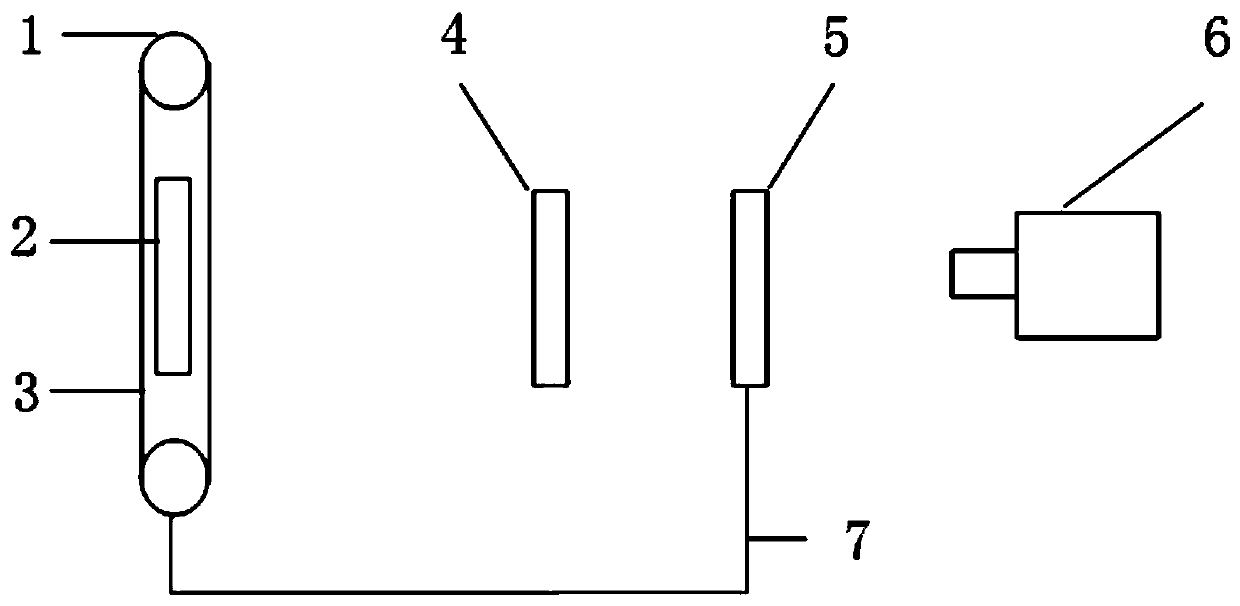
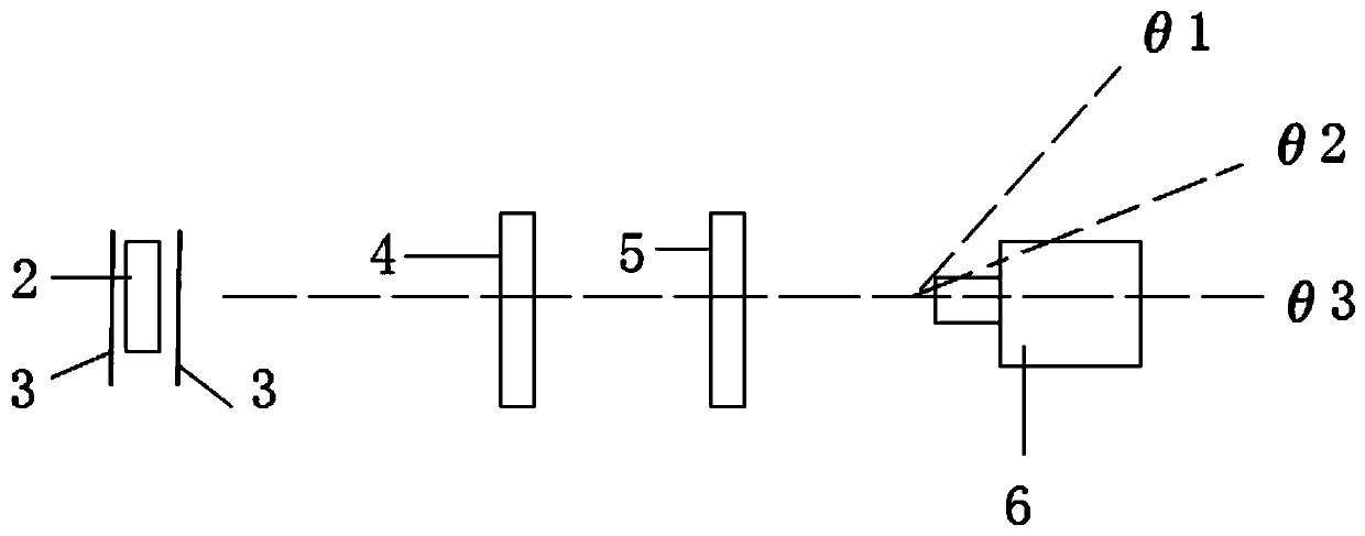
[0038] Such as figure 1 , figure 2 As shown, the spark detection probe performance testing device is equipped with a thermal radiation source 2, an optical component and a clamping device from left to right. The optical assembly includes a light shielding part, a distance attenuator 4 and an aperture 5 . The probe 6 to be tested is clamped on the clamping device.
[0039] The device can detect various types of spark detection probes. According to different types of probes 6 to be tested, different heat radiation sources 2 can also be selected, such as blackbody radiation sources, resistance wires, gas welding torches, and the like.
[0040] As the propagation distance increases, thermal radiation will naturally attenuate. The distance attenuator 4 is used to attenuate heat radiation, so that the overall footprint of the device is small, and the resulting heat signal is weakened within a relatively short distance. The distance attenuator 4 can be of optical fiber type, suc...
Embodiment 2
[0053] Like Embodiment 1, the belt 3 is a net-like or frame-like structure, on which a base is detachably connected. The connection method can be bonding, clamping and the like.
[0054] In this way, various types of light-transmitting regions can be replaced without changing the belt 3 . The material of the substrate can be selected from heat-resistant materials, and cooling devices can be arranged at other positions of the light-shielding part for cooling the belt 3 . For example, a cooling device is installed at pulley 1.
Embodiment 3
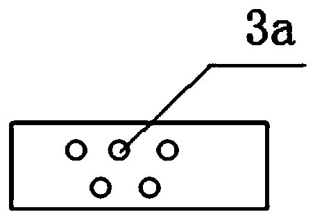
[0056] Such as Figure 3 to Figure 6 As shown, the style of the light transmission area can be selected and adjusted according to the actual performance to be measured, such as the porous first light transmission area 3a, the circular hole-shaped second light transmission area 3b, the rectangular third light transmission area 3c, The elliptical fourth light-transmitting region 3d.
PUM
 Abstract
Description
Claims
Application Information
 - R&D
- Intellectual Property
- Life Sciences
- Materials
- Tech Scout
- Unparalleled Data Quality
- Higher Quality Content
- 60% Fewer Hallucinations
Browse by: Latest US Patents, China's latest patents, Technical Efficacy Thesaurus, Application Domain, Technology Topic, Popular Technical Reports.
© 2025 PatSnap. All rights reserved.Legal|Privacy policy|Modern Slavery Act Transparency Statement|Sitemap|About US| Contact US: help@patsnap.com


