A packaging structure and method of an optical fiber Fab sensor for temperature measurement in nuclear facilities

A Faber sensor and packaging structure technology, applied in measuring devices, thermometers, measuring heat, etc., can solve the problems that the armored structure is difficult to meet the response to high-speed temperature changes, restricts the development of nuclear power temperature measurement devices, and the size of the armored structure is large. Achieve the effect of ensuring high-speed time response characteristics, increasing versatility and consistency, and small size

Active Publication Date: 2020-08-18
CHONGQING UNIV
View PDF8 Cites 0 Cited by
  • Summary
  • Abstract
  • Description
  • Claims
  • Application Information

AI Technical Summary

Problems solved by technology

[0003] The armored structure must not only ensure the insulation performance requirements of the thermocouple during normal operation, but also meet the mechanical strength requirements of nuclear power safety, which makes the armored structure larger in size and longer in temperature response time, so it is difficult for the armored structure to meet The requirement of high-speed temperature change response restricts the development of nuclear power temperature measurement devices

Method used


Image

  • A packaging structure and method of an optical fiber Fab sensor for temperature measurement in nuclear facilities
  • A packaging structure and method of an optical fiber Fab sensor for temperature measurement in nuclear facilities
  • A packaging structure and method of an optical fiber Fab sensor for temperature measurement in nuclear facilities

Examples


Embodiment 1

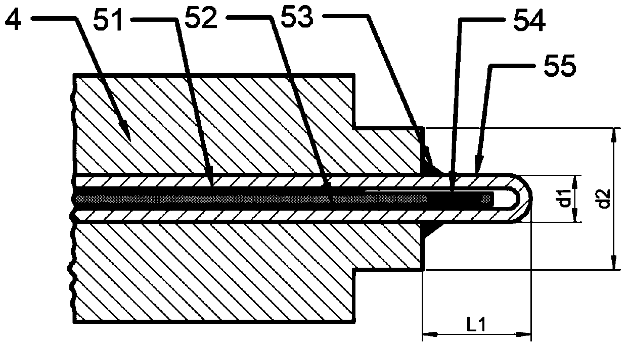
[0035] In order to ensure the high temperature stability and high sensitivity of the optical fiber Fab sensor, such as Figure 4 The shown femtosecond laser 501 processes the large-cavity long fiber optic sensor of the fiber optic sensor of the present invention on the bare optical fiber 52, and its steps are:

[0036] S2: Using a femtosecond laser 501 to manufacture a fiber optic F-P cavity 54 on the top of the bare fiber 52 using a single-point positioning method to form a fiber-optic F-P sensor, which can work at a high temperature of 800°C without attenuation;

[0037] S2: Clean the optical fiber sensor produced in step S1 with acetone, coat it with a single-end thin layer of high-temperature-resistant adhesive 51, and penetrate from the center into a single-end sealed capillary steel pipe 55 with an outer diameter of 0.5 mm and an inner diameter of 0.2 mm. In the process, the high temperature resistant glue is cured, so that the optical fiber Fab cavity region 54 is in a ...

Embodiment 2

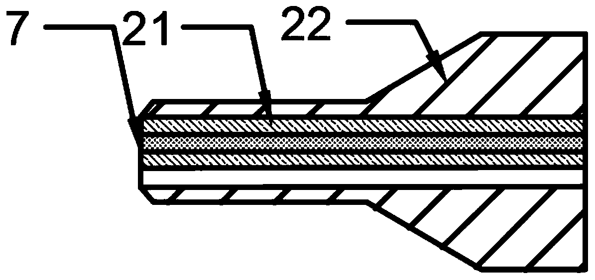
[0043] In order to ensure the high temperature stability and high sensitivity of the optical fiber Fab sensor, such as Figure 5 The shown hollow-core optical fiber (or hollow-core photonic crystal fiber) 503 makes the large-cavity long Fab sensor, and its steps are:

[0044] (1) Cut off and polish the right end face of the bare optical fiber 52 and the left end face of the hollow-core optical fiber (or hollow-core photonic crystal fiber) 503, and weld them together with an optical fiber fusion splicer;

[0045] (2) According to the designed length, the right end face of the hollow-core optical fiber (or hollow-core photonic crystal fiber) 503 is cut off and polished;

[0046] (3) Cut off and polish the left end face of another section of bare optical fiber 52 again, and weld it with the right end face of the hollow-core optical fiber (or hollow-core photonic crystal fiber) 503 with an optical fiber fusion splicer to form an optical fiber Fab cavity 54. The sensor can work at...


PUM

PropertyMeasurementUnit
lengthaaaaaaaaaa

Abstract

The invention relates to a packaging structure and method of an optical fiber Fab sensor used for temperature measurement of nuclear facilities, and belongs to the technical field of optical fiber sensing. The structure includes single-mode optical fiber, heat insulating guide post, flange base, capillary steel pipe, stainless steel armored tube and optical fiber Fab sensor; the method is: make an optical fiber Fab sensor at the top of the single-mode optical fiber; into a capillary steel tube sealed at one end, and bonded and fixed with high-temperature-resistant adhesive; penetrate the capillary steel tube into a stainless steel armored tube with an inner diameter of 0.5 mm, so that the sensing part is exposed about 2 to 3 mm outside the tube; The stainless steel armored tube is installed into the flange base from both ends; the joints between the capillary steel tube and the stainless steel armored tube, and the stainless steel armored tube and the base are welded and sealed; the sensor is annealed as a whole. The invention breaks through the size limitation of the thermocouple sensor on the packaging structure, and provides a sensing method with high-speed temperature response for temperature measurement of nuclear facilities.

Description

technical field [0001] The invention belongs to the technical field of optical fiber sensing, and relates to a packaging structure and method of an optical fiber F-P sensor used for temperature measurement of nuclear facilities. Background technique [0002] The safe operation of nuclear facilities is very important. Once an accident occurs, the consequences will be unimaginable. Therefore, it is necessary to monitor the key parameters of nuclear facilities in real time. This operation is not only a basic means to ensure the normal operation of nuclear facilities, but also an important way to prevent catastrophic accidents. measure. Temperature is one of the important parameters for safety monitoring of nuclear facilities. Since the most important task of nuclear facilities is safety, any temperature monitoring device must ensure the absolute safety of nuclear facilities in order to meet the expected measurement requirements. Long-term research and application assessment ha...

Claims


Application Information

Patent Timeline
Patent Type & Authority Patents(China)
IPC IPC(8): G01K11/32B23K26/20
CPCG01K11/32B23K26/206
Inventor 陈伟民邵高杰邵斌张伟章鹏雷小华刘显明
Owner CHONGQING UNIV
Why Eureka
Try Eureka