An upward hanging type downhole oil-water separation pipe string

A technology of oil-water separation and oil-water separator, which is applied in wellbore/well components, measurement, production fluid, etc. It can solve problems such as difficult water injection control, high implementation risk, and complex string structure, and achieve breakthrough in size limitation and applicable Effects with a wide range and simple structure

Active Publication Date: 2020-12-04
CHINA NAT OFFSHORE OIL CORP +1
View PDF7 Cites 0 Cited by
  • Summary
  • Abstract
  • Description
  • Claims
  • Application Information

AI Technical Summary

Problems solved by technology

After the former is separated, the reinjection water directly enters the casing annulus, so it is difficult to control the reinjection water. If the annulus reinjection water is collected by running a packer or a leather cup, and the large-diameter annulus is measured and adjusted The device and string structure are complex, and the risk of implementation is relatively high. At the same time, the large size also has certain requirements for well deviation
Although the latter can be equipped with a control device on the reinjection pipe, due to the limitation of the size of the wellbore, the parallel structure of the reinjection pipe and the electric submersible pump limits the displacement and lifting capacity of the electric submersible pump on the one hand, and on the other hand cannot install a large displacement pump. Control device for downhole oil-water separation
At the same time, in small cased wells, the latter is spatially more difficult to realize the downhole monitoring function of oil-water separation, so downhole oil-water separation monitoring technology also needs to find a more suitable string structure

Method used


Image

  • An upward hanging type downhole oil-water separation pipe string

Examples


Embodiment Construction

[0018] In order to further understand the invention content, characteristics and effects of the present invention, the following examples are given, and detailed descriptions are as follows in conjunction with the accompanying drawings:

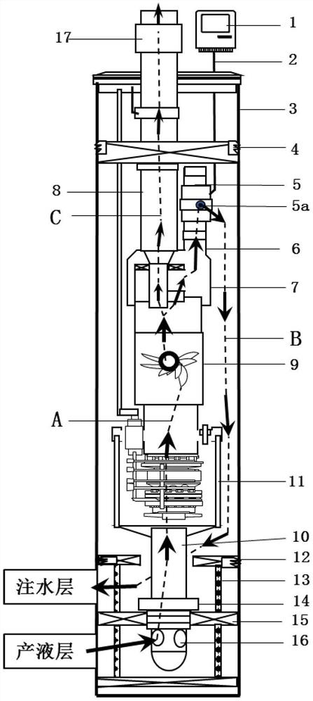
[0019] see figure 1 , an upwardly suspended downhole oil-water separation and measurement and adjustment string, including a perforated pipe 16 connected by oil pipes from bottom to top, an insertion seal 14, a canned pump system 11, a downhole oil-water separator 9, and a downhole oil-water separator. The upward suspension type separating mechanism 7 that separator 9 is connected. The separation mechanism 7 is a three-way structure, the upper end of which is two ports, the first port is connected to the lifting oil pipe 8, the second port is connected to the return oil pipe 6, and the lower port is connected to the outlet of the downhole oil-water separator, forming an upward hanging structure.

[0020] The insertion seal 14 is inserted in...


PUM


Abstract

The invention discloses an upward suspension type underground oil-water separation pipe column. The pipe column comprises a perforated pipe, an inserted seal, a filling pump system and an oil-water separator which are connected from bottom to top through an oil pipe. The pipe column also comprises a separation joint, wherein the separation joint is connected with the oil-water separator and is ofa three-way structure, the upper end of the separation joint is provided with two ports, the first port is connected with a lifting oil pipe, the second port is connected with an oil return oil pipe,a lower port is connected with an outlet of the oil-water separator, and an upward suspension type structure is formed. Three channels are formed in the pipe column and include the channel for outputliquid of an output liquid layer to enter the oil-water separator, the re-injection channel used after test modification of separated low-oil-content output water and the oil-rich output liquid lifting channel. The pipe column has the advantages that the separated lifting channel is connected with the re-injection channel, so that the problems that a conventional suspension type underwater oil-water separation structure electric pump liquid output channel is connected with the re-injection channel in parallel, the size of a casing pipe is limited and re-injected test modification is difficultare solved; large-displacement underground oil-water separation and re-injected water monitoring are achieved.

Description

technical field [0001] The invention discloses a downhole oil-water separation and measuring and adjusting pipe string, in particular to an upwardly suspended downhole oil-water separation pipe string. Background technique [0002] The downhole oil-water separation technology has been widely studied and applied in recent years. The oil-rich fluid is lifted to the surface by using the downhole oil-water separation device, and the low-oil reinjection water is injected into another section of the same well to form the same well oil-water downhole separation and injection-production system. It will greatly increase the utilization rate of the wellbore, and play the role of increasing production and efficiency, saving energy and reducing emissions. The development of efficient downhole oil-water separation needs to be combined with downhole monitoring and control technology. According to changes in oil well fluid production, water content, and water absorption capacity of the wat...

Claims


Application Information

Patent Timeline
Patent Type & Authority Patents(China)
IPC IPC(8): E21B43/38E21B43/40E21B43/20E21B47/00
CPCE21B43/385E21B47/00
Inventor 王瑶张成富罗昌华王胜郭沛文洪秀玫
Owner CHINA NAT OFFSHORE OIL CORP
Why Eureka
Try Eureka