Packaging structure and method of optical fiber Fabry-Perot sensor for temperature measurement of nuclear facility
A Fab sensor and packaging structure technology, applied in measuring devices, thermometers, measuring heat, etc., can solve the problems that armored structures are difficult to respond to high-speed temperature changes, restrict the development of nuclear power temperature measurement devices, and have large armored structures. To achieve the effect of ensuring high-speed time response characteristics, increasing versatility and consistency, and small size
- Summary
- Abstract
- Description
- Claims
- Application Information
AI Technical Summary
Problems solved by technology
Method used
Image
Examples
Embodiment 1
[0034] In order to ensure the high temperature stability and high sensitivity of the optical fiber Fab sensor, such as Figure 4 The shown femtosecond laser 501 processes the large-cavity long fiber optic sensor of the fiber optic sensor of the present invention on the bare optical fiber 52, and its steps are:
[0035] S2: Using a femtosecond laser 501 to manufacture a fiber optic F-P cavity 54 on the top of the bare fiber 52 using a single-point positioning method to form a fiber-optic F-P sensor, which can work at a high temperature of 800°C without attenuation;
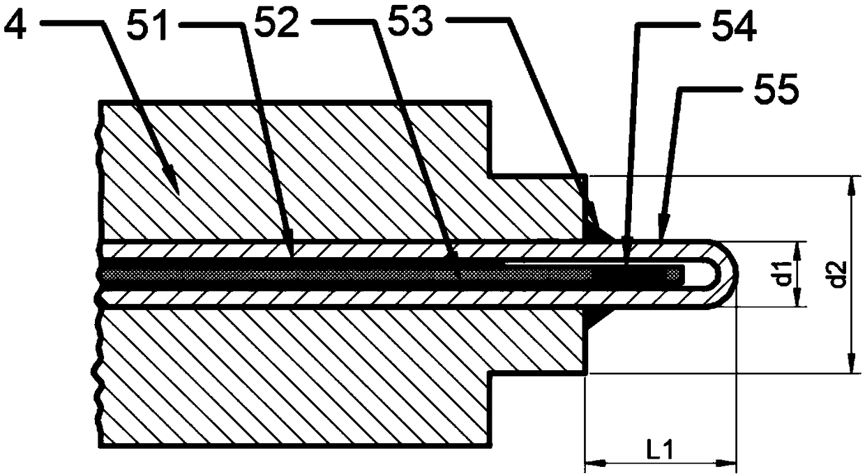
[0036] S2: Clean the optical fiber sensor produced in step S1 with acetone, coat it with a single-end thin layer of high-temperature-resistant adhesive 51, and penetrate from the center into a single-end sealed capillary steel pipe 55 with an outer diameter of 0.5 mm and an inner diameter of 0.2 mm. In the process, the high temperature resistant glue is cured, so that the optical fiber Fab cavity region 54 is in a ...
Embodiment 2
[0042] In order to ensure the high temperature stability and high sensitivity of the optical fiber Fab sensor, such as Figure 5 The shown hollow-core optical fiber (or hollow-core photonic crystal fiber) 503 makes the large-cavity long Fab sensor, and its steps are:
[0043] (1) Cut off and polish the right end face of the bare optical fiber 52 and the left end face of the hollow-core optical fiber (or hollow-core photonic crystal fiber) 503, and weld them together with an optical fiber fusion splicer;
[0044] (2) According to the designed length, the right end face of the hollow-core optical fiber (or hollow-core photonic crystal fiber) 503 is cut off and polished;
[0045] (3) Cut off and polish the left end face of another section of bare optical fiber 52 again, and weld it with the right end face of the hollow-core optical fiber (or hollow-core photonic crystal fiber) 503 with an optical fiber fusion splicer to form an optical fiber Fab cavity 54. The sensor can work at...
PUM
| Property | Measurement | Unit |
|---|---|---|
| length | aaaaa | aaaaa |
Abstract
Description
Claims
Application Information
 - R&D
- Intellectual Property
- Life Sciences
- Materials
- Tech Scout
- Unparalleled Data Quality
- Higher Quality Content
- 60% Fewer Hallucinations
Browse by: Latest US Patents, China's latest patents, Technical Efficacy Thesaurus, Application Domain, Technology Topic, Popular Technical Reports.
© 2025 PatSnap. All rights reserved.Legal|Privacy policy|Modern Slavery Act Transparency Statement|Sitemap|About US| Contact US: help@patsnap.com


