
Rolling bearing unit

A technology of rolling bearings and bearings, applied in the field of rolling bearings

Inactive Publication Date: 2019-02-05
NTN CORP
View PDF15 Cites 0 Cited by
  • Summary
  • Abstract
  • Description
  • Claims
  • Application Information

AI Technical Summary

Problems solved by technology

[0018] However, even if the gap is provided between the annular support frame of the sealing member and the outer ring of the bearing, or between the annular support frame and the outer ring of the bearing, it is unavoidable that the gap caused by the sealing member When manufacturing error, thermal expansion difference with bearing, etc. become larger to some extent

Method used


Image

  • Rolling bearing unit
  • Rolling bearing unit
  • Rolling bearing unit

Examples


Embodiment Construction

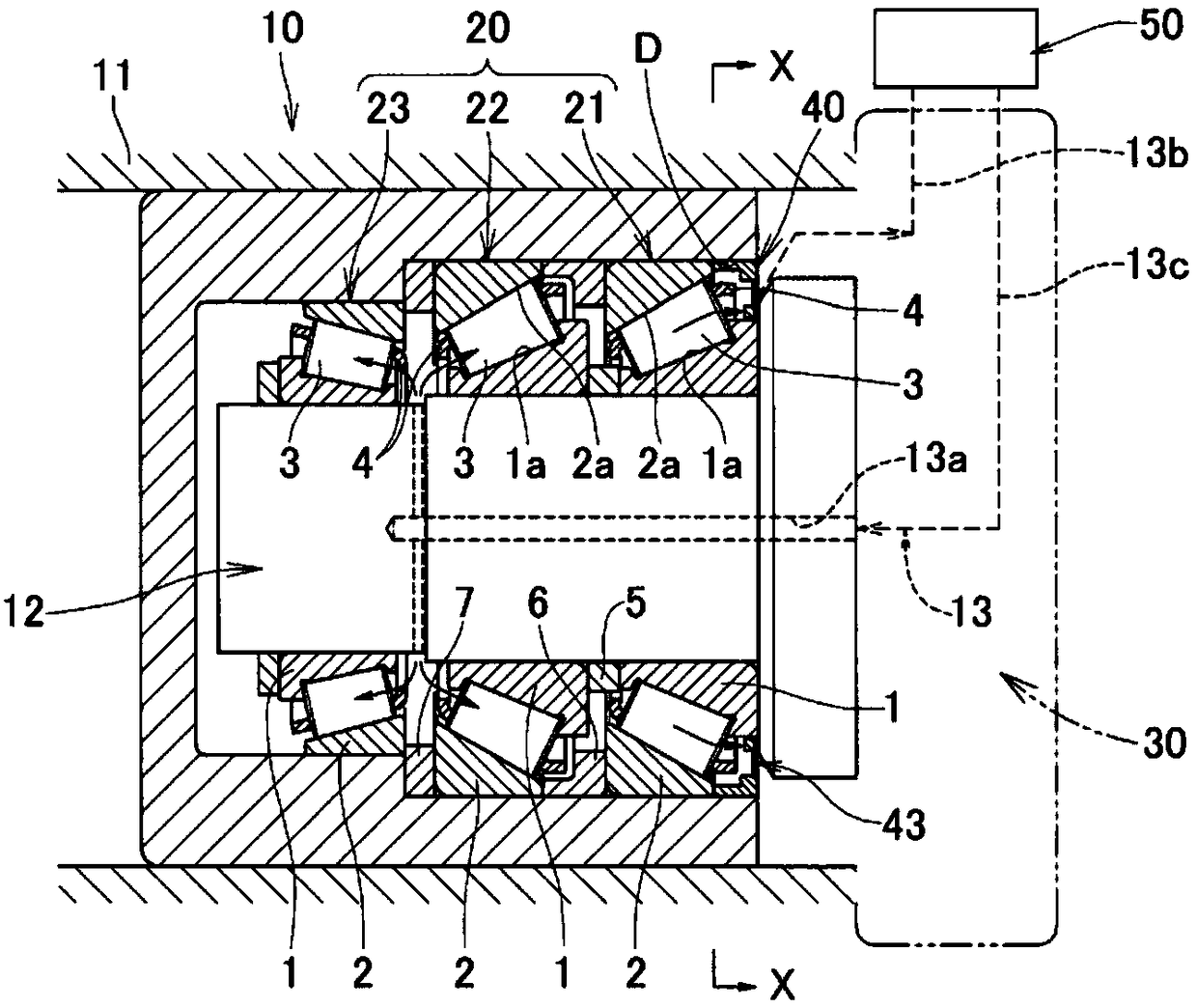
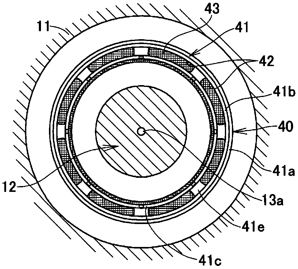
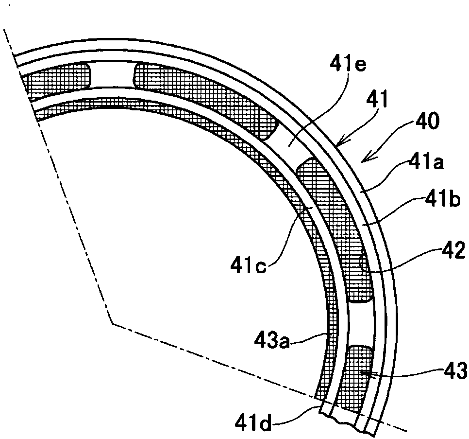
[0060] Below, based on the attached Figure 1 to Figure 19 , an embodiment of the rolling bearing of the present invention will be described by taking a casing used in an oil pump as an example.

[0061] figure 1 Numeral 10 is an oil pump, which has a bearing unit 20 and an operating mechanism unit 30 including a pump rotor (not shown) that sucks and compresses oil and discharges it.

[0062] The bearing unit 20 includes three rolling bearings 21 , 22 , and 23 arranged in parallel and lubricated with oil inside the casing 11 .

[0063] The rotating shaft 12 of the oil pump is supported by these rolling bearings 21 , 22 , 23 , and the pump rotor of the operating mechanism unit 30 is driven by the rotating shaft 12 to suck, compress, and discharge oil.

[0064] Each of the rolling bearings 21, 22, 23 is a well-known bearing including an inner ring (inner raceway) 1, an outer ring (outer raceway) 2, and a rolling bearing arranged between the raceway surfaces 1a, 2a of the inne...


PUM


Abstract

The present invention is a rolling bearing unit, wherein: a seal member (40) includes a support frame (41) and a filter (43) which are combined or integrally formed, and a window hole (42) of the support frame is sealed by the filter (43); the inner diameter of the support frame (41) is set to be a size such that a passage (9) through which a lubricant oil passes is formed between the support frame (41) and the outer diameter surface of an inner ring (1); and the filter (43) protrudes in the radially inner side of the inner diameter surface of the support frame (41) and the radial inner end ofthe protruding part comes into contact with the inner ring (1), or the filter (43) surrounds the outer circumference of the inner ring (1) with a small gap with respect to the inner ring (1), the gapbeing smaller than the mesh size of the filter (43).

Description

technical field [0001] The present invention relates to a rolling bearing that has an oil circulation path inside and lubricates itself by the oil passing through the circulation path, and particularly relates to a rolling bearing that prevents foreign matter (metal peeling pieces) that are generated due to damage to the internal rolling surface and the like from being released to the outside of the bearing. Outflow function of the rolling bearing unit. Background technique [0002] Rolling bearings are incorporated into the movable parts of conveying equipment, industrial machinery, and other various equipment. Such equipment has an operating mechanism portion requiring lubrication in addition to the oil-lubricated rolling bearing, and the operating mechanism portion and the rolling bearing often have a structure that is lubricated with common oil. Examples of the above-mentioned operating mechanism portion include a meshing portion between gears, a sliding contact portion...

Claims


Application Information

Patent Timeline
Patent Type & Authority Applications(China)
IPC IPC(8): F16C33/78F16C19/38F16C19/52F16C33/66F16C33/76F16J15/16
CPCF16C33/667F16C33/7869F16C33/82F16C19/364F16C19/56F16C19/546F16C33/80F16C33/6659F16C19/38
Inventor 山本直太东穗翔太内村宙史
Owner NTN CORP
Learn More