Automatic cutting device for production of customized plates

A cutting device and sheet material production technology, which is applied in the direction of positioning device, feeding device, manufacturing tools, etc., can solve the problems that the arc cannot be adjusted, the sheet cannot be fixed, and there is no waste collection device, so as to improve the working environment and improve practicality. sexual effect

Inactive Publication Date: 2019-02-12
TIANJIN YUANZHUO AUTOMATION EQUIP MFG CO LTD
0 Cites 4 Cited by

AI-Extracted Technical Summary

Problems solved by technology

[0003] The purpose of the present invention is to provide an automatic cutting device for customized plate production to solve the problem that the current cutting device proposed by t...

Method used

As preferably, the upper end of gas strut 18 is connected with baffle plate 19 by hinge shaft, and the lower end of gas strut 18 is connected with waste bin 2, and baffle plate 19 is provided with two groups altogether, and baffle plate 19 Gas struts 18 are respectively installed on both sides of the waste bin 2, the two ends of the support frame 20 are affixed to both sides of the workbench 4, and the support frame 20 is equidistantly installed inside the workbench 4, so that when cutting The generated waste falls from the distance between the support frame 20 into the waste bin 2, and the waste bin 2 is provided to collect the board waste generated during cutting, so as to prevent the waste from floating in the air, causing environmental pollution or Corrosion of the human body, effectively improving the cutting working environment.
Both sides of cutting blade 8 are provided with protective shell 9...

Abstract

The invention discloses an automatic cutting device for production of customized plates. The automatic cutting device comprises a chassis, a chute, a tightening bolt, a cutting blade, a first telescopic rod, a rotary frame, a gear, a pneumatic strut and support frames. A scrap bin is embedded in the left side of the chassis. The chute is embedded in a workbench. A fixed block is connected to the bottom end of the tightening bolt, and a first fixed bolt is arranged at the upper end of the fixed block. Protection shells are arranged on the two sides of the cutting blade. The upper end of the pneumatic strut is connected with a baffle through a hinging shaft, and the lower end of the pneumatic strut is connected with the scrap bin. The support frames are fixedly connected to the inner side ofthe workbench at equal intervals. According to the automatic cutting device, the plates of different sizes can be fixed, cutting of any radian can be conducted, meanwhile the scraps generated duringcutting can also be collected, and practicability and safety of the automatic cutting device are improved greatly.

Application Domain

Technology Topic

Image

  • Automatic cutting device for production of customized plates
  • Automatic cutting device for production of customized plates
  • Automatic cutting device for production of customized plates

Examples

  • Experimental program(1)

Example Embodiment

[0018] The technical solutions in the embodiments of the present invention will be clearly and completely described below in conjunction with the accompanying drawings in the embodiments of the present invention. Obviously, the described embodiments are only a part of the embodiments of the present invention, rather than all the embodiments. Based on the embodiments of the present invention, all other embodiments obtained by those of ordinary skill in the art without creative work shall fall within the protection scope of the present invention.
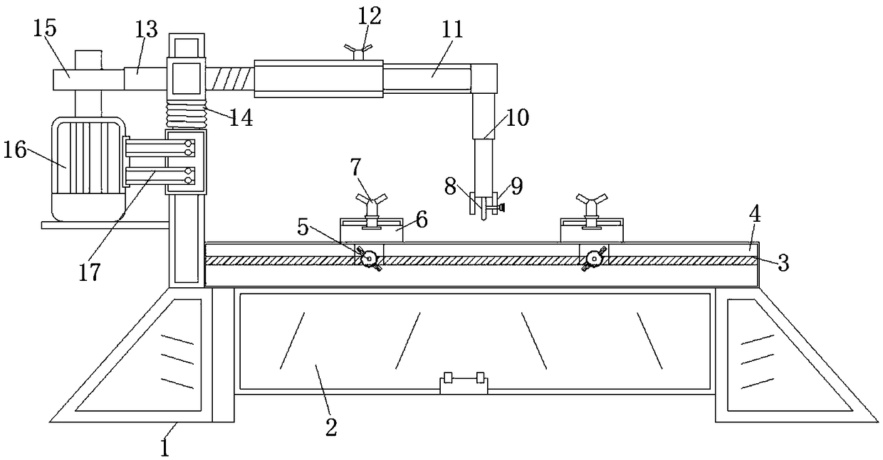
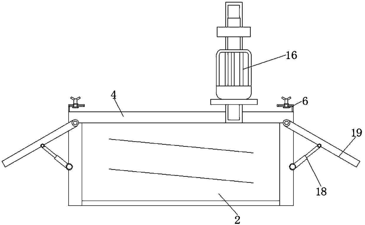
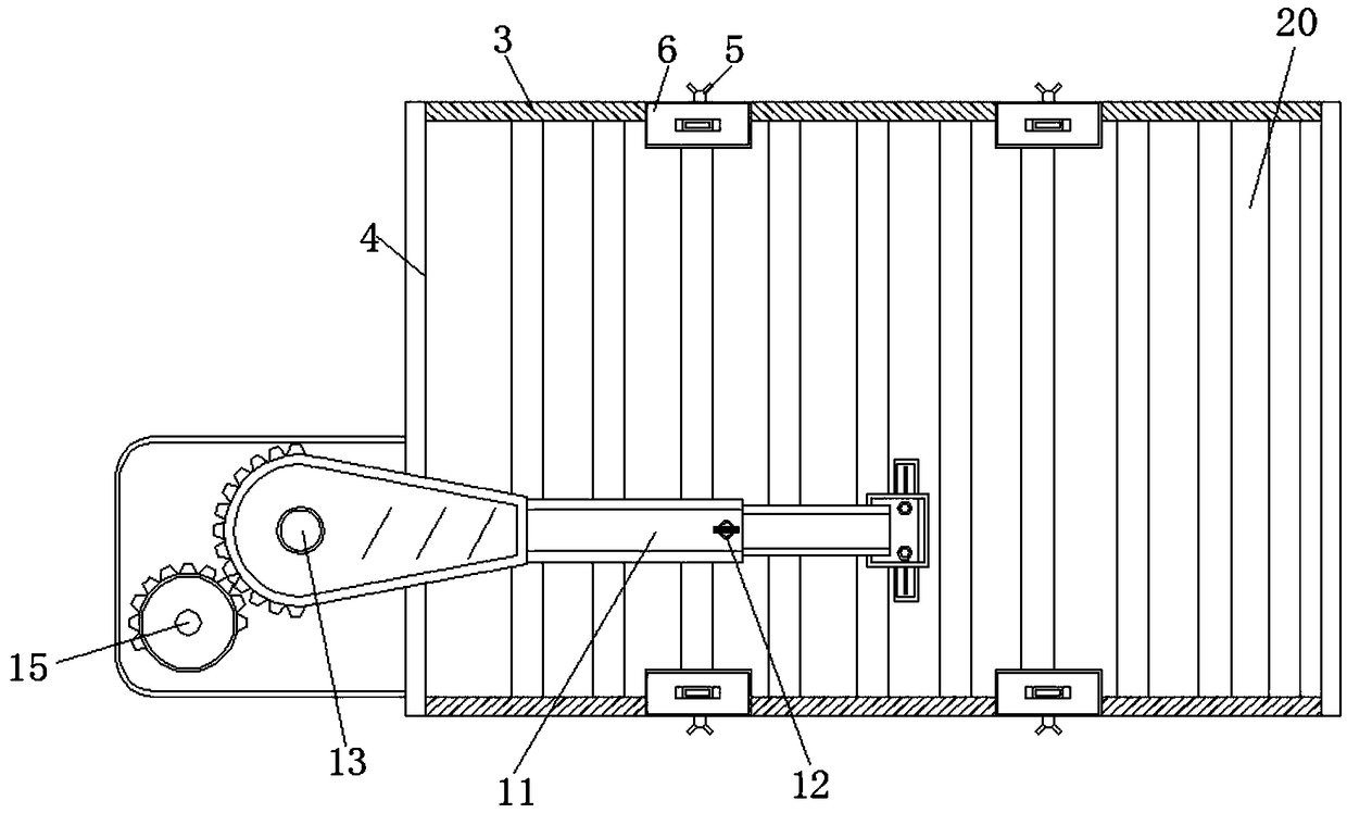
[0019] See Figure 1-3 , An embodiment provided by the present invention:
[0020] An automatic cutting device for customized sheet production, including a base frame 1, a sliding groove 3, a tightening bolt 5, a cutting blade 8, a first telescopic rod 10, a rotating frame 13, a gear 15, a gas strut 18 and a support frame 20, A waste bin 2 is embedded on the left side of the underframe 1, and a chute 3 is embedded on the workbench 4. As a preference, the bottom end of the tightening bolt 5 is connected with a fixing block 6, and the upper end of the fixing block 6 is provided with a first The fixing bolt 7, the tightening bolt 5 are provided with washers, and the two sides of the workbench 4 are provided with sliding seams. The size of the washers of the tightening bolt 5 is larger than the sliding seam size of the workbench 4, and the bottom end of the tightening bolt 5 passes through the work The table 4 is connected with the fixed block 6. The tightening bolt 5 can lock the moving fixed block 6. A sliding block is arranged at the lower end of the fixed block 6, and the outer dimension of the sliding block is the same as the inner dimension of the sliding groove 3. 3 is embedded in the workbench 4, the fixed block 6 and the workbench 4 are in a sliding connection structure. The fixed blocks 6 are provided with four groups, and the fixed blocks 6 are respectively installed on both sides of the workbench 4. The set of slidable fixed blocks 6 can fix plates of different sizes on the worktable 4 for cutting, so as to prevent the plates from being separated from the worktable 4 or inaccurate cutting because the plates cannot be fixed when cutting.
[0021] A protective shell 9 is provided on both sides of the cutting blade 8. As a preference, a second telescopic rod 11 is connected to the upper end of the first telescopic rod 10, and a second fixing bolt 12 is provided on the second telescopic rod 11, and the rotating frame 13 A torsion spring 14 is provided. The lower end of the gear 15 is connected with a motor 16 and the motor 16 is connected to the turret 13 through a bracket 17. The left side of the turret 13 is set as a semi-arc gear, and the gear 15 is a semi-serrated gear. The semi-arc gear on 13 engages with the gear 15, and is provided with a rotating frame 13 and a second telescopic rod 11. The rotating frame 13 drives the second telescopic rod 11 to arc-shaped rotation for cutting work. At the same time, by adjusting the second telescopic rod The length of 11 can be cut in different arcs, so that the device can cut the plate at any arc, which greatly improves the practicability of the device.
[0022] Preferably, the upper end of the gas strut 18 is connected to the baffle 19 through a hinge shaft, and the lower end of the gas strut 18 is connected to the waste bin 2. There are two sets of baffles 19, and the baffles 19 are air supported. The rods 18 are installed on both sides of the waste bin 2 respectively, the two ends of the support frame 20 are fixedly connected to both sides of the workbench 4, and the support frame 20 is equidistantly installed inside the workbench 4, which can make the waste generated during cutting The scraps fall from the spacing of the support frame 20 into the scrap bin 2. The scrap bin 2 is provided to collect the scraps of the board produced during cutting to avoid the scraps floating in the air, causing environmental pollution or eroding the human body. Effectively improve the cutting working environment.
[0023] Working principle: When in use, the device is connected to an external power source to provide power support for the motor 16 in the device;
[0024] Place the plate to be cut on the worktable 4, and make both sides of the plate be embedded in the fixing block 6, rotate the first fixing bolt 7 so that the first fixing bolt 7 fixes the plate and tightens the cutting blade 8 Attached to the board, the protective shell 9 can prevent the cutting blade 8 from hurting the operator. In addition, the fixed block 6 is slid in the chute 3, and the fixed block 6 is locked by rotating the tightening bolt 5. Fixed board;
[0025] Subsequently, the motor 16 is turned on to rotate the gear 15 and drive the turret 13 to rotate. Since the gear 15 is set as a semi-serrated gear, the turret 13 is set as an arc gear, and the turret 13 is provided with a torsion spring 14. When the motor When 16 drives the gear 15 to rotate, the turret 13 makes an arc movement. At the same time, when the gear 15 rotates to the non-serrated part, the turret 13 is disengaged from the gear 15. At this time, the torsion spring 14 restores the turret 13 to its original position. , Repeatedly, performing arc-shaped movement, and at the same time, by adjusting the length of the second telescopic rod to change the length of the arc-shaped diameter, the plate can be cut in different arcs;
[0026] When cutting, the waste generated will fall into the waste bin 2 through the gap of the adjacent support frame 20 for collection, and the baffle 19 will be opened by the gas strut 18, and the waste bin 2 To clean up the scraps, on the one hand, it prevents the scraps from spreading and pollutes the environment. On the other hand, it also protects the operators from the erosion of the scraps, which greatly improves the cutting environment.
[0027] For those skilled in the art, it is obvious that the present invention is not limited to the details of the foregoing exemplary embodiments, and the present invention can be implemented in other specific forms without departing from the spirit or basic characteristics of the present invention. Therefore, from any point of view, the embodiments should be regarded as exemplary and non-limiting. The scope of the present invention is defined by the appended claims rather than the foregoing description, and therefore it is intended to fall within the claims. All changes within the meaning and scope of equivalent elements of are included in the present invention. Any reference signs in the claims should not be regarded as limiting the claims involved.

PUM

no PUM

Description & Claims & Application Information

We can also present the details of the Description, Claims and Application information to help users get a comprehensive understanding of the technical details of the patent, such as background art, summary of invention, brief description of drawings, description of embodiments, and other original content. On the other hand, users can also determine the specific scope of protection of the technology through the list of claims; as well as understand the changes in the life cycle of the technology with the presentation of the patent timeline. Login to view more.

Similar technology patents

Classification and recommendation of technical efficacy words

  • Improve practicality
  • Improve working environment

Pig manure centralized treatment and resource utilization method

Owner:SHANGHAI RUIDAO ENERGY SAVING ENVIRONMENTAL PROTECTION SCI & TECH CO LTD
Why Eureka
Try Eureka