Waxing impeller

An impeller and blade technology, applied in the field of waxing impellers, can solve the problems of poor finish of finished brick surface, high loss rate of waxing impellers, large wax consumption, etc. The effect of reduced installed capacity

Inactive Publication Date: 2019-02-12
广东工科机电有限公司
View PDF0 Cites 0 Cited by
  • Summary
  • Abstract
  • Description
  • Claims
  • Application Information

AI Technical Summary

Problems solved by technology

[0004] However, the current brick surface grinding, waxing and polishing process still has defects.
The intuitive result is that the finish of the brick surface is not high and uneven, the waxing impeller loss rate is high, the wax consumption is large, and it is not environmentally friendly

Method used


Image

  • Waxing impeller
  • Waxing impeller
  • Waxing impeller

Examples


Embodiment 1

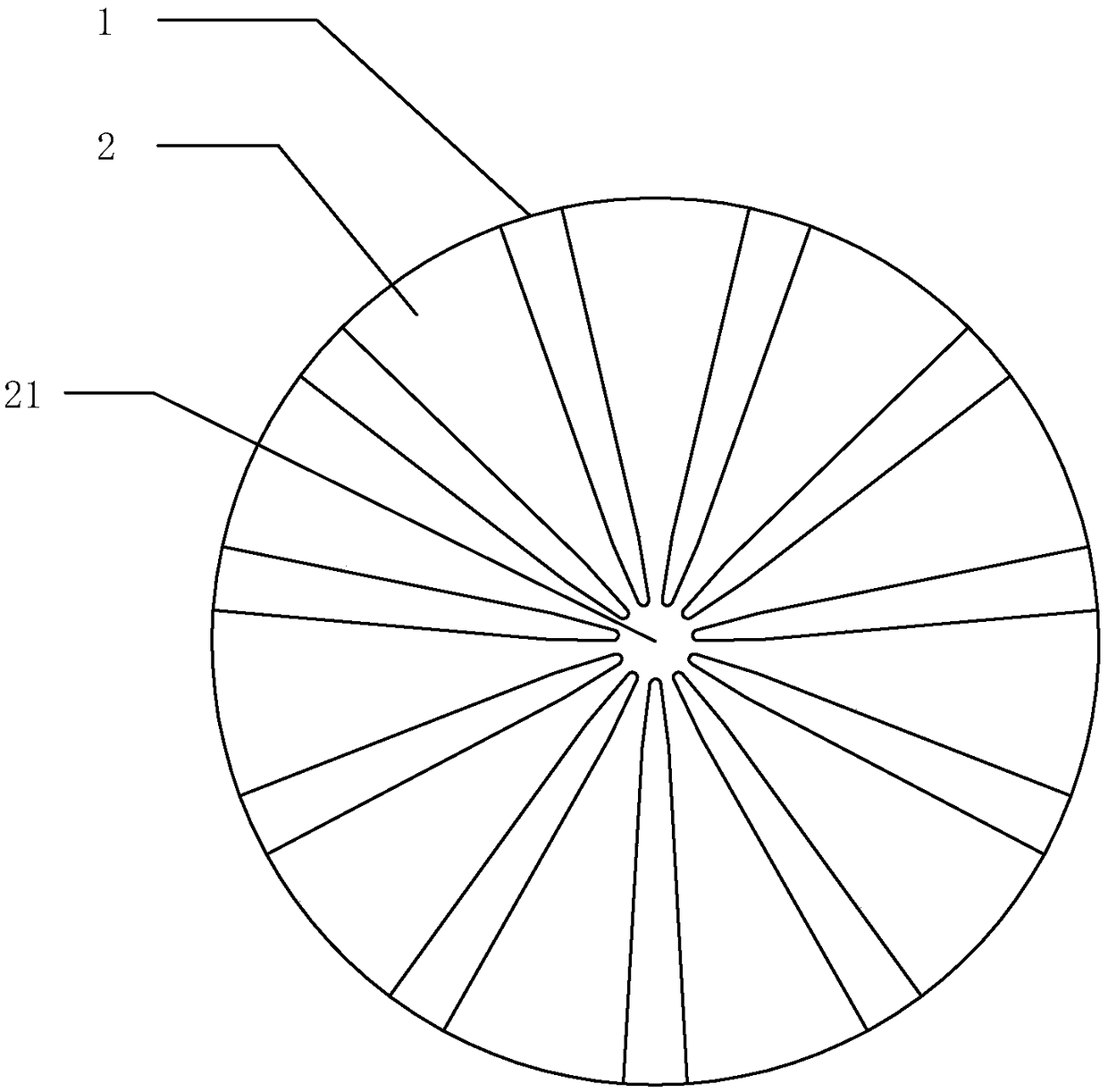
[0024] Continue to refer to figure 2 , in this embodiment, the ends of the plurality of blades 2 are continuous with each other to form a continuous area 21 . Such a structural design is more convenient to manufacture, and the liquid film can easily spread freely from the part of the blade that has been overstocked to other blade positions with uneven pressure and less waxy water below, and can automatically adjust and adapt the coverage without affecting the impeller. Originally, there is an inherent chip removal space between blades and blades, so it has a good grinding and polishing effect.

Embodiment 2

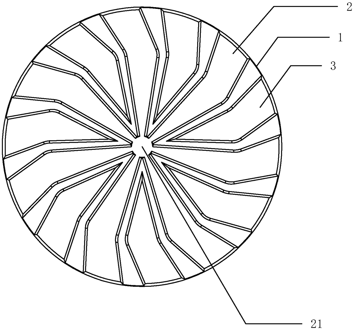
[0026] refer to image 3 , the basis of this embodiment is roughly the same as that of Embodiment 1, but different changes are made to the continuity scheme of the blades, and the continuous means of discrete intervals are adopted. That is to say, there are at least two discontinuous blade groups on the disc body 1, and each of the discontinuous blade groups includes two blades 2 that are continuous at the ends of each other and the blades that are located between the two blades 2 and are also from the lower part of the disc body 1. At least one auxiliary blade 3 protrudes from the surface, and the auxiliary blade 3 and the blade 2 are not connected to each other.

[0027] This embodiment introduces the concepts of intermittent blade group and auxiliary blade, but it is added for the convenience of structural description. In specific production practice, the auxiliary blade and the blade can be regarded as the same physical part, except that the ends of the blades are connecte...


PUM


Abstract

The invention discloses a waxing impeller. The waxing impeller comprises a disk body and a plurality of blades, wherein the blades protrude out of the lower surface of the disk body; the blades are integrally distributed around the center of the disk body; the head ends of the blades are located at the peripheral edge of the disk body, and the tail ends of the blades are located in the center position of the disk body; the tail ends of at least two of the multiple blades are connected continuously. According to the waxing impeller, the shape and structure of an existing impeller are improved;under the action of centrifugal force generated during operation and the capillary phenomenon, a liquid film below one blade can extend to the location below the other blade from the continuous location, so that the covering area of the liquid film is effectively increased, the waxing effect is enhanced, and the grinding and polishing efficiency is improved. The waxing impeller can be applied to various occasions where workpieces need to be waxed and polished.

Description

technical field [0001] The invention relates to the field of grinding and polishing of ceramic tiles, in particular to a waxing impeller. Background technique [0002] After rough grinding and medium-precision grinding of ceramic tiles, it is necessary to enter the next step of grinding and polishing the brick surface. When working, the ceramic tiles are sent to the polishing station of the ceramic polishing machine. A waxing impeller is installed at the bottom of the grinding head of the machine facing the brick surface. The grinding head is pressed down so that the lower surface of the waxing impeller is in contact with the brick surface. , and then the impeller is driven to rotate at a high speed, and the brick surface is polished and polished. In order to enhance the smooth effect of waxing, facilitate chip removal and prevent dry burning, wax water must be sprayed on the brick surface at this time, that is, the impeller is grinding. Nowadays, there is a wax-water liqui...

Claims


Application Information

Patent Timeline
Patent Type & Authority Applications(China)
IPC IPC(8): B24D13/02
CPCB24D13/02
Inventor 龙其瑞黄军韦金卫
Owner 广东工科机电有限公司
Why Eureka
Try Eureka