
Mold structure capable of automatically shearing sprue in mold for plastic pipe

An automatic technology for plastic pipe fittings, which can be used in household appliances, tubular objects, and other household appliances. It can solve the problems of increasing costs, easily scratching the molding surface of pipe fittings, and increasing the external size of the mold, so as to save costs and save labor in assembly. , The effect of cutting position stability

Active Publication Date: 2019-02-12
LINHAI WEIXING NEW BUILDING MATERIALS CO LTD
View PDF8 Cites 0 Cited by
  • Summary
  • Abstract
  • Description
  • Claims
  • Application Information

AI Technical Summary

Problems solved by technology

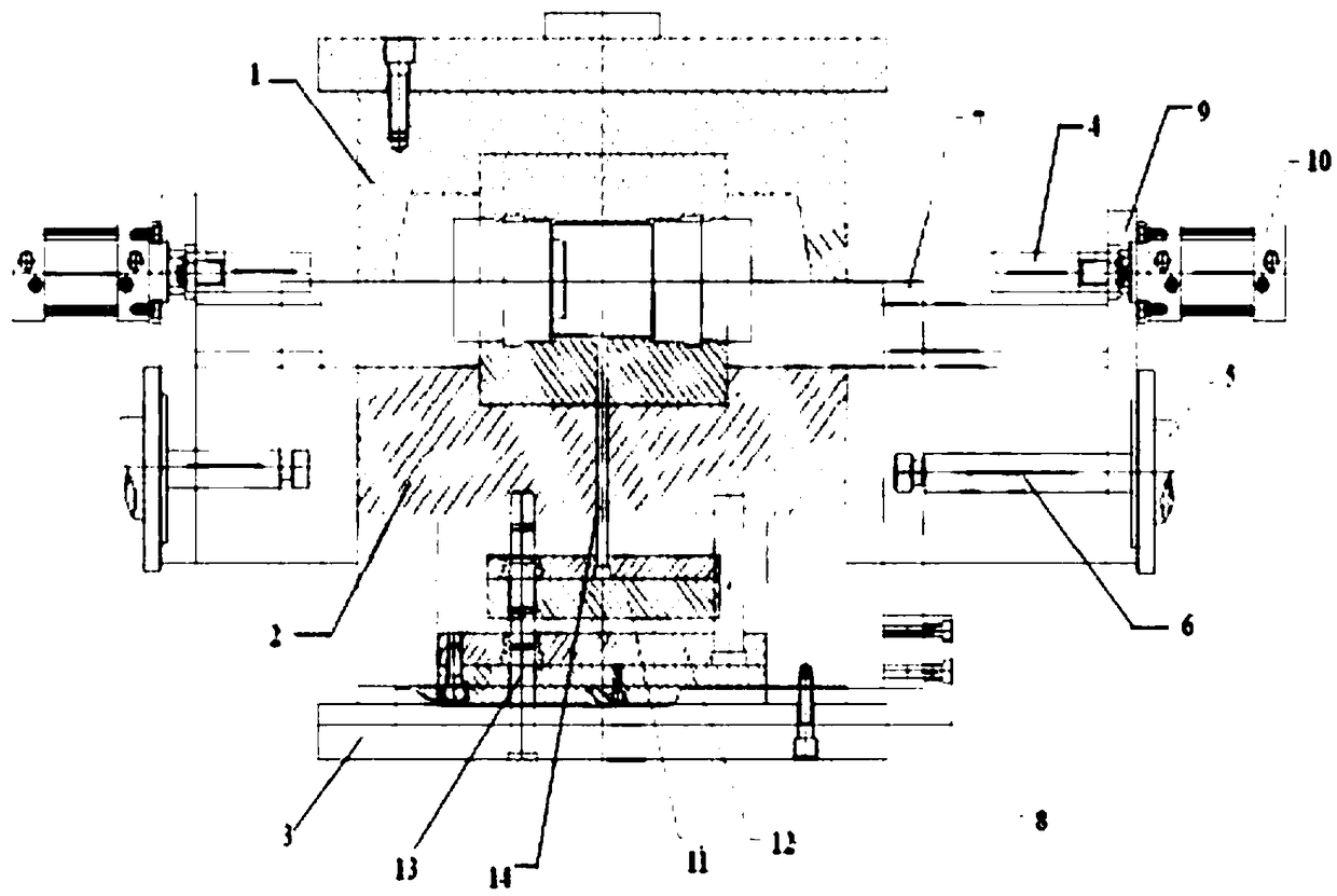
[0005] The automatic shearing side gate mechanism in the pipe injection mold needs the thimble to eject the formed pipe first, and then the cylinder drives the cutter to complete the shearing. When the pipe is tilted during ejection, it is agreed that the pipe is not in place and easy to cut. Scratch the molding surface of the pipe fittings, and the mold needs to install the position of the cylinder, which increases the external size of the mold and requires a larger injection molding machine, which increases the cost

Method used


Image

  • Mold structure capable of automatically shearing sprue in mold for plastic pipe
  • Mold structure capable of automatically shearing sprue in mold for plastic pipe
  • Mold structure capable of automatically shearing sprue in mold for plastic pipe

Examples


Embodiment Construction

[0038] In order to further illustrate the technical means and effects of the present invention to achieve the intended purpose of the invention, the specific implementation, structure, features, and effects of the present invention will be described in detail below with reference to the drawings and preferred embodiments.

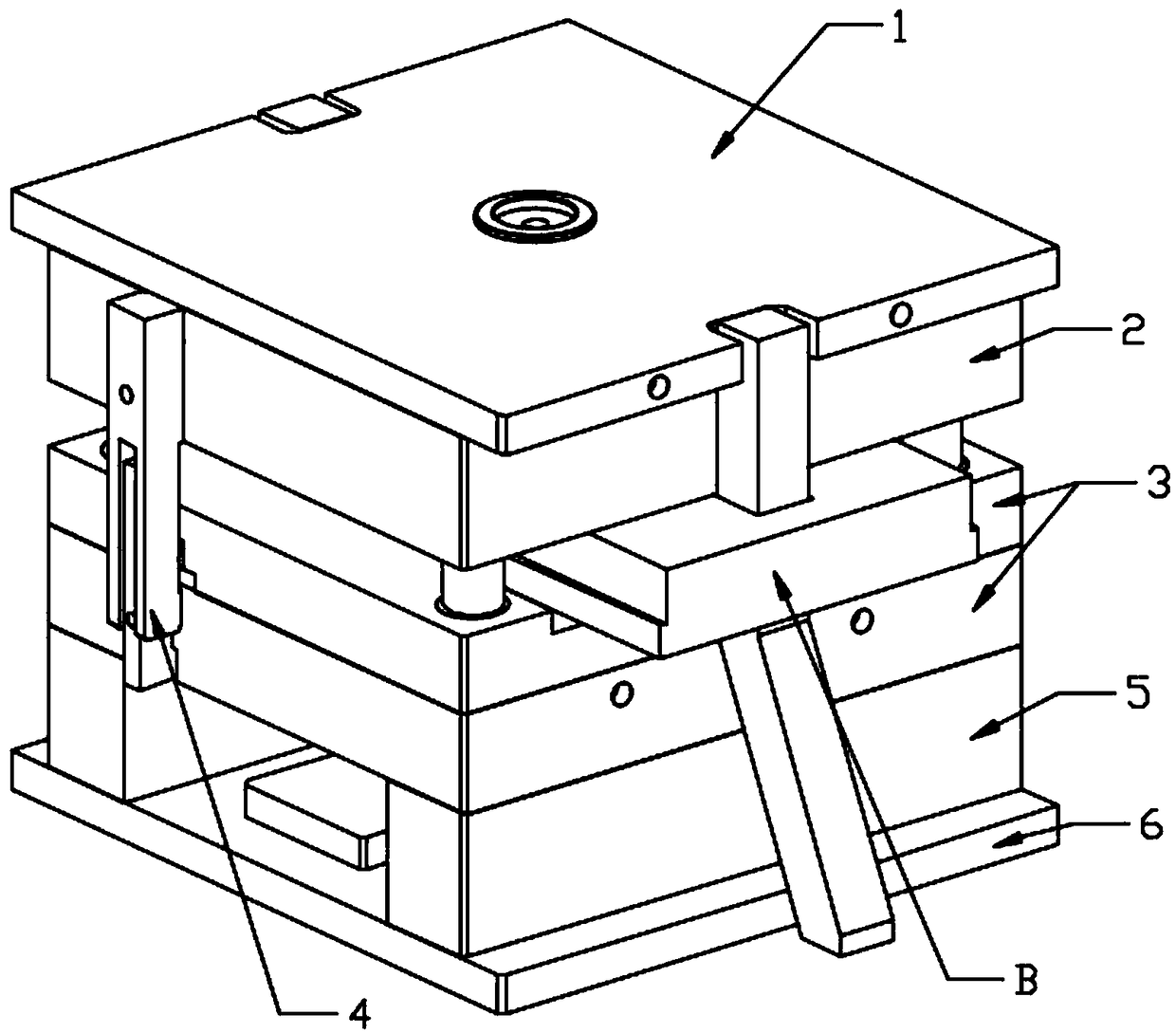
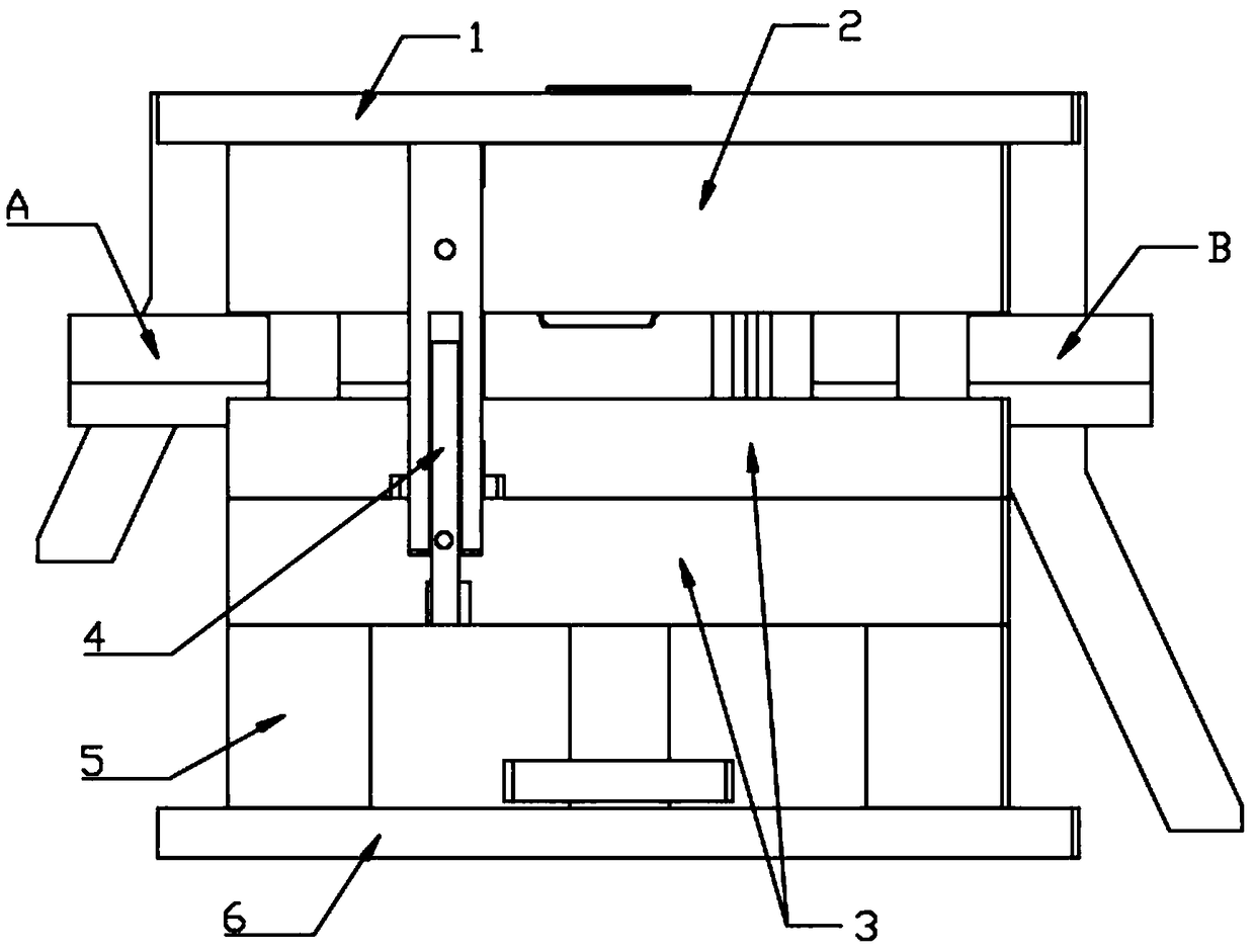
[0039] See Figure 2-6 , The in-mold automatic shear gate mold structure for plastic pipe fittings of the first embodiment of the present invention includes: upper composite plate 1, fixed mold 2, movable mold 3, core pulling A and core pulling B slidably connected to movable mold 3. Pull hook 4, mold foot 5, lower composite board 6.

[0040] The upper composite board 1 and the fixed mold 2 are connected and fixed. The movable mold 3 is connected and fixed with the lower compound board 6 through mold feet 5. The fixed mold 2 is fixed with a first bending pin 2A and a second bending pin 2B for driving the core pulling A and the core pulling B to move between the...


PUM


Abstract

The invention relates to the technical field of injection molds, in particular to a mold structure capable of automatically shearing a sprue in a mold for a plastic pipe. The mold structure capable ofautomatically shearing the sprue in the mold for the plastic pipe comprises a movable mold body, a fixed mold body, a pulling core A and a pulling core B, wherein the pulling core A and the pulling core B are connected to the movable mold body in a sliding mode; a blade which corresponds to the sprue and is used for cutting off the sprue is connected and fixed to the movable mold body; and the pulling core B drives the plastic pipe to move towards the blade after the pulling core A and the movable mold body are separated from the plastic pipe, so that the blade cuts off the sprue which is connected to the plastic pipe. According to the mold structure capable of automatically shearing the sprue in the mold for the plastic pipe, a scraper plate is arranged and fixes the blade, the plastic pipe moves in the core de-molding direction under the holding force of the core to the position of the blade to cut off the sprue, and therefore the phenomena that the plastic pipe is inclined and thelike can be avoided, and the cutting position is stable and accurate.

Description

Technical field [0001] The invention relates to the technical field of injection moulds, in particular to an in-mould automatic shear gate mould structure for plastic pipe fittings. Background technique [0002] In the mold industry production, various molds and tools are used for injection blow molding, extrusion, die casting or forging molding, smelting, stamping and other methods to obtain the required products. In short, molds are tools used to make molded objects. This kind of tool is composed of various parts, and different molds are composed of different parts. In the plastic mold manufacturing industry, there are more and more appearance plastic products. The requirements for such appearance products are very strict. Flow marks, burrs, gates and other phenomena have put forward higher requirements for the manufacture of plastic molds. [0003] After the product is injection molded in production, there are still gates on the product, such as lap gate or side gate. The plast...

Claims


Application Information

Patent Timeline
IPC IPC(8): B29C45/33B29C45/38B29L23/00
CPCB29C45/261B29C45/33B29C45/38B29L2023/22
Inventor 马胜孙宽褚红波
Owner LINHAI WEIXING NEW BUILDING MATERIALS CO LTD
Learn More