
Base band sheet-pulling device for processing conducting copper foil adhesive tape

A technology of adhesive tape and base tape, which is applied in the directions of transportation and packaging, winding strips, sending objects, etc. It can solve the problems of low processing efficiency and slow pulling speed, so as to improve work efficiency, prevent the base tape from loosening, and improve stability. Effect

Inactive Publication Date: 2020-01-10
湖北富和冠电子材料有限公司
View PDF0 Cites 0 Cited by
  • Summary
  • Abstract
  • Description
  • Claims
  • Application Information

AI Technical Summary

Problems solved by technology

[0003] In the process of production and processing of conductive copper foil tape, it is often necessary to cut the base tape. Generally, the mechanical mechanism is used to move the cutting knife to carry out the cutting operation, and the pull-tab mechanism is used to feed the base tape. In the prior art, the base tape The pulling speed is slow, which makes the overall processing efficiency low

Method used


Image

  • Base band sheet-pulling device for processing conducting copper foil adhesive tape
  • Base band sheet-pulling device for processing conducting copper foil adhesive tape
  • Base band sheet-pulling device for processing conducting copper foil adhesive tape

Examples


Embodiment 1

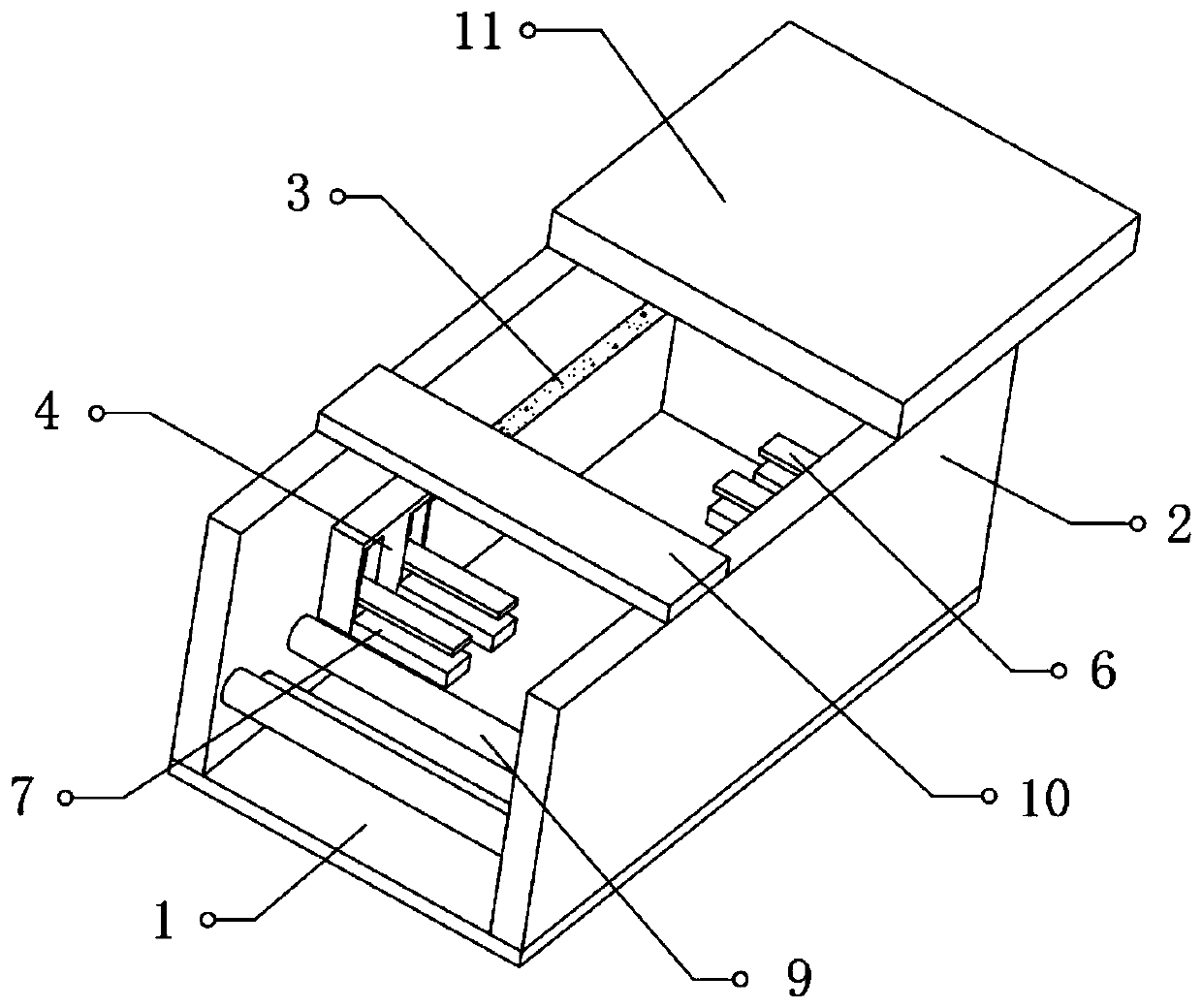
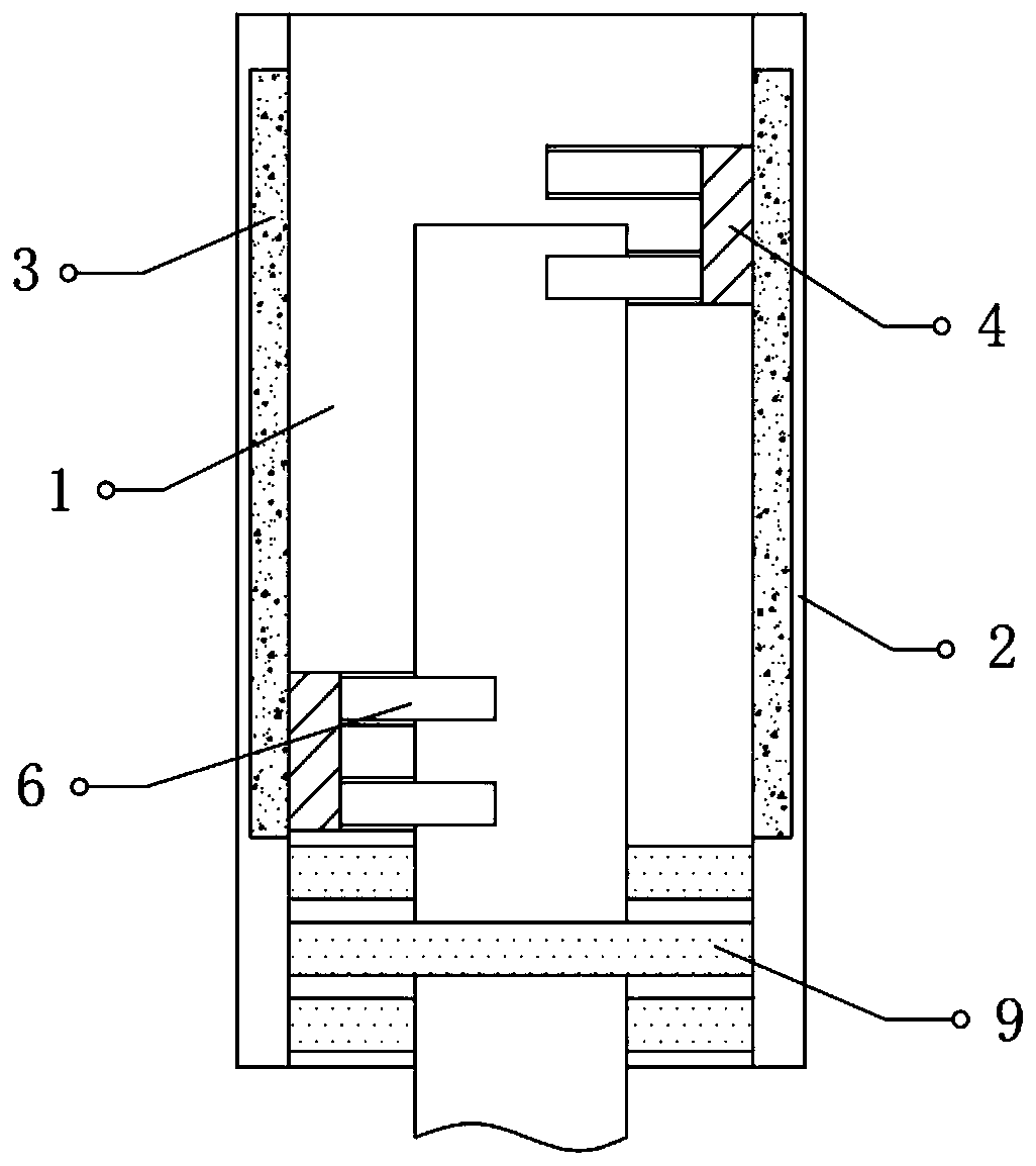
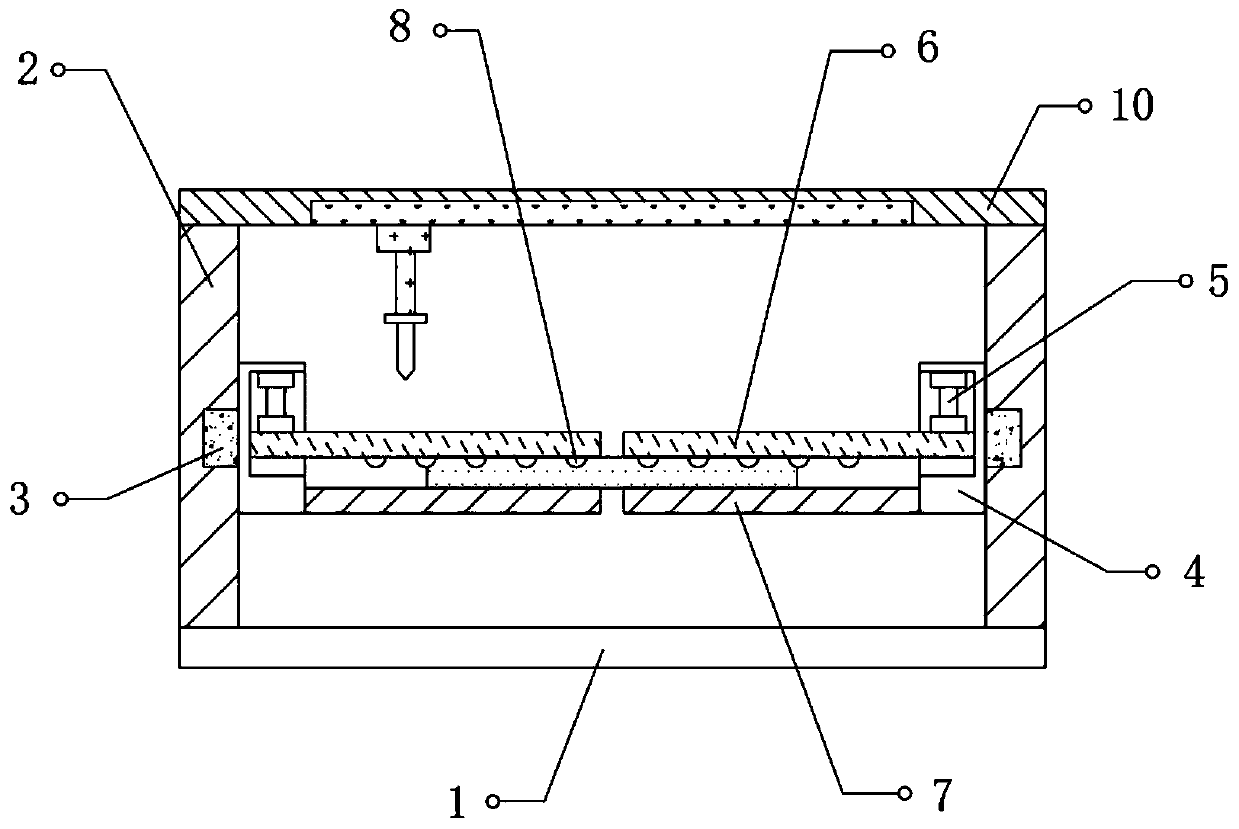
[0024] refer to Figure 1-3 , a base tape pull-tab device for conductive copper foil tape processing, including a base 1, a fixing frame 2 is fixed at both ends of the top outer wall of the base 1, and a first electric guide rail 3 arranged horizontally is fixed at one end of the fixing frame 2, the second One end of an electric guide rail 3 is connected with a clamping mechanism, and the sum of the widths of the two clamping mechanisms is less than the width between the two fixed frames 2, and the same cutting frame 10 is fixed on one side of the top of the two fixed frames 2 , and the bottom of the cutting frame 10 is provided with a cutting mechanism, the other side of the top of the two fixed frames 2 is fixed with the same retrieving frame 11, and the bottom of the retrieving frame 11 is provided with a retrieving mechanism.

[0025] In the present invention, the cutting mechanism is provided with a second electric guide rail fixed on the bottom of the cutting frame 10, a...

Embodiment 2

[0030] refer to Figure 1-2 with Figure 4 , a base tape pull-tab device for conductive copper foil tape processing, further, a mounting groove is opened on the top outer wall of the support plate 7, and a vacuum chuck 12 is fixed on the inner wall of the mounting groove.

[0031] Working principle: Further, the device is provided with an installation slot on the top of the support plate 7, and a vacuum suction cup 12 is fixed in the installation slot to connect with the vacuum pump through the air pipe, so that when the support plate 7 and the pressure plate 6 are used to clamp the base tape, the vacuum suction cup 12 is used to clamp the base tape. The adsorption effect on the baseband enhances the stability of the baseband being clamped.


PUM


Abstract

The invention discloses a base band sheet-pulling device for processing a conducting copper foil adhesive tape. The device comprises a base. Fixed racks are fixed to two ends of the outer wall of thetop of the base, a horizontally arranged first electric guide rail is fixed to one end of each fixed rack, one end of the first electric guide rail is connected to a clamping mechanism, the sum of widths of the two clamping mechanisms is smaller than the width between the fixed racks, a same cropping rack is fixed to one sides of the tops of the fixed racks, a cropping mechanism is arranged at thebottom of the cropping rack, a same reclaiming rack is fixed to the other sides of the tops of the two fixed racks, and a reclaiming mechanism is arranged at the bottom of the reclaiming rack. By moving the clamping mechanisms to pull a base band, the clamping mechanism on the other end is located on the side close to an auxiliary roller clamps the base band. After cropping, the clamping mechanism on the side close to the auxiliary clamping roller moves to pull a sheet and the clamping mechanism at the other end resets for a follow-up clamping operation, so that the integral working efficiency is improved.

Description

technical field [0001] The invention relates to the technical field of conductive copper foil tape processing, in particular to a base tape pull-tab device for processing conductive copper foil tape. Background technique [0002] Copper foil tape is a kind of metal tape, mainly used in electromagnetic shielding, divided into two types: electrical signal shielding and magnetic signal shielding. Electrical signal shielding mainly relies on the excellent electrical conductivity of copper itself, while magnetic shielding requires the rubber surface of copper foil tape The conductive substance "nickel" is used to achieve the effect of magnetic shielding, so it is widely used in mobile phones, notebook computers and other digital products. [0003] In the process of production and processing of conductive copper foil tape, it is often necessary to cut the base tape. Generally, the mechanical mechanism is used to move the cutting knife to carry out the cutting operation, and the pu...

Claims


Application Information

Patent Timeline
Patent Type & Authority Applications(China)
IPC IPC(8): B65H20/16B65H20/00B65H35/00
CPCB65H20/00B65H20/16B65H35/0073B65H35/008B65H2406/366B65H2701/172
Inventor 刘超
Owner 湖北富和冠电子材料有限公司
Learn More