Electric vehicle intelligent alternating current charging system

A technology of AC charging and AC charging piles, which is applied in the field of electric power, can solve the problems of increasing the electricity load of the community, unbalanced three-phase load, and overload protection of the power distribution facilities of the community, so as to avoid the waste of abundant electricity and maintain the three-phase load balanced effect

Pending Publication Date: 2019-02-12
EAST GRP CO LTD
View PDF5 Cites 3 Cited by
  • Summary
  • Abstract
  • Description
  • Claims
  • Application Information

AI Technical Summary

Problems solved by technology

For example, in a residential area, after the car owner drives home at night, he will insert the charging gun into the electric vehicle immediately, and the charging pile will start charging the electric vehicle. Increase the power load of the community, resulting in a decrease in the grid voltage, and even cause the overload protection of the power distribution facilities of the community to interrupt the power supply of the community
In order to avoid such phenomena, community properties generally do not allow the construction of a large number of charging piles, or limit the charging time of community owners for electric vehicles.
This will bring a lot of inconvenience to the promotion and use of electric vehicles
[0004] On the other hand, the current domestic electricity consumption in the community is basically a single-phase load. Since the load connected to each phase is uncertain, the power consumption time is also uncertain, and there may be loads connected to or connected to each phase at any time. Disconnection, which will lead to unbalanced three-phase load, resulting in low voltage of overloaded phase and increase of neutral current
[0005] The current AC charging pile is also a single-phase load. If the charging pile is connected to a phase line with a heavy load, even if the other two-phase loads are leftover, the charging pile cannot be used.

Method used


Image

  • Electric vehicle intelligent alternating current charging system

Examples


Embodiment 1

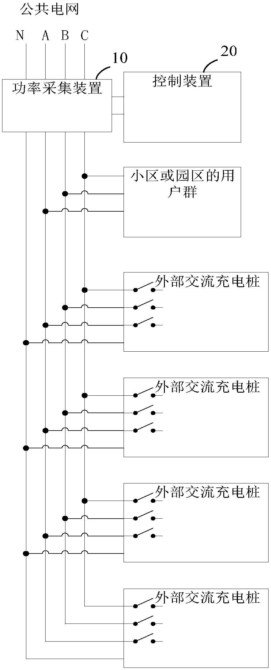
[0024] Please refer to the attached figure 1 , which is a schematic structural diagram of an electric vehicle intelligent AC charging system provided in Embodiment 1 of the present invention, the system specifically includes:

[0025] The power acquisition device 10 and the control device 20, the power acquisition device 10 is set at the input end of the public grid, the input end of the public grid is a three-phase four-wire system, including three-phase lines respectively A phase, B phase and C phase phase, and the neutral line N line (zero line), the power users of the public grid include at least one external AC charging pile, and in actual situations often include the user group of the community or park;

[0026] The power collection device 10 is connected with the control device 20, and is used to collect power for the three-phase and neutral wires of the public power grid, so as to determine the load condition of each phase, and send the load condition to the control d...


PUM


Abstract

The invention discloses an electric vehicle intelligent alternating current charging system, which comprises a power acquisition device and a control device, the power acquisition device is arranged at an input terminal of a public supply network, and the input terminal of the public supply network is a three-phase four-wire system; electricity users of thepublic supply network include one or moreexternal alternating current charging piles; the power acquisition device is connected with the control device, used for power acquisition ofthree phases and a zero line of the public supply networkto determine the load condition of each phase and sending the load conditions to the control device; and the control device is used for generating control signals according to the load conditions andsending the control signals to the external alternating current charging piles, so as to control the external alternating current charging piles to operate from the phase line with heavy load to the phase line with light load. According to the technical scheme, on the basis of giving priority to residential electricity consumption and production electricity consumption, the rest available electricity is dynamically distributed to the charging piles, power resources are fully utilized, and obstacles are cleared for the charging piles entering communities.

Description

technical field [0001] Embodiments of the present invention relate to the field of electric power technology, and in particular to an intelligent AC charging system for electric vehicles. Background technique [0002] At present, electric vehicles have been widely developed. For the convenience of charging, electric vehicles are equipped with AC charging ports and DC charging ports. Correspondingly, there are AC charging piles and DC charging piles. DC charging piles charge faster, but are more expensive, and are more suitable for public charging occasions; while AC charging piles are slower in charging speed, but cheaper, and are more suitable for residential parking lots or Parking lots in industrial parks, because cars park in these parking lots for a longer period of time. [0003] However, in the residential districts or industrial parks that were built earlier, the power supply capacity of the power grid was only designed to meet the residential electricity consumptio...

Claims


Application Information

Patent Timeline
Patent Type & Authority Applications(China)
IPC IPC(8): B60L53/31B60L53/63
CPCY02T10/7072Y02T10/70Y02T90/12
Inventor 李绍辉荣校邓锐锋
Owner EAST GRP CO LTD
Why Eureka
Try Eureka