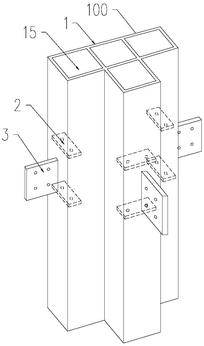
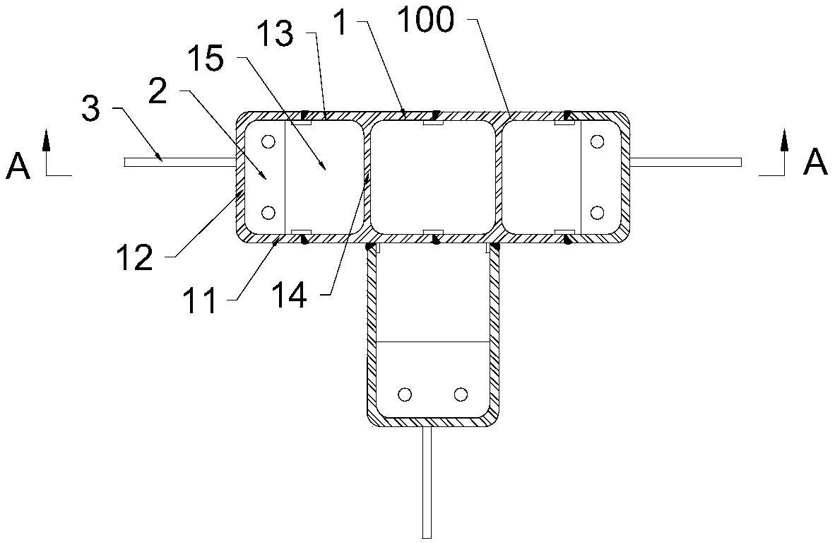
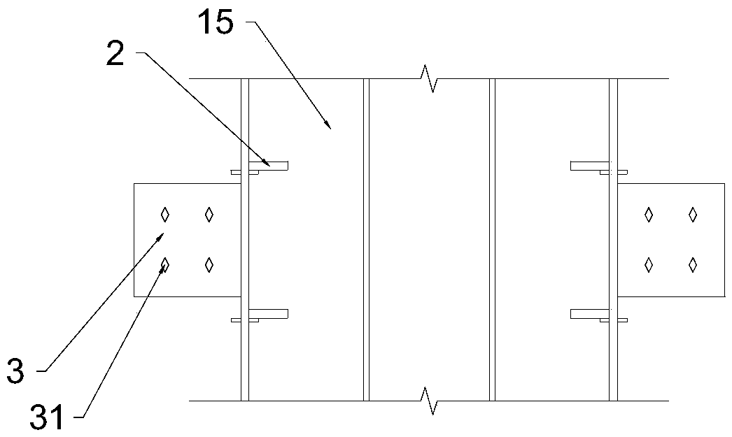
Special-shaped column assembly and beam column connecting joint structure

A node structure and special-shaped column technology, applied in the direction of columns, pier columns, pillars, etc., can solve the problems of heavy welding workload of special-shaped columns, slow concrete pouring speed, and low structural strength of partitions, so as to reduce welding workload and pour Dense, increase the effect of perfusion speed

Pending Publication Date: 2019-02-12
北京和筑科技有限公司
View PDF4 Cites 0 Cited by
  • Summary
  • Abstract
  • Description
  • Claims
  • Application Information

AI Technical Summary

Problems solved by technology

[0008] In view of the shortcomings of the existing methods, this application proposes a special-shaped column assembly and a beam-column connection node structure to solve the existing problems in the prior art that have special-shaped columns with heavy welding workload, slow concrete pouring speed, incomplete pouring or partition structures Technical problems of defects such as low strength

Method used


Image

  • Special-shaped column assembly and beam column connecting joint structure
  • Special-shaped column assembly and beam column connecting joint structure
  • Special-shaped column assembly and beam column connecting joint structure

Examples


Embodiment Construction

[0041] The present application is described in detail below, and examples of embodiments of the present application are shown in the drawings, wherein the same or similar reference numerals denote the same or similar components or components having the same or similar functions throughout. Also, detailed descriptions of known technologies will be omitted if they are not necessary to illustrate the features of the present application. The embodiments described below by referring to the figures are exemplary only for explaining the present application, and are not construed as limiting the present application.

[0042] Those skilled in the art can understand that, unless otherwise defined, all terms (including technical terms and scientific terms) used herein have the same meanings as commonly understood by those of ordinary skill in the art to which this application belongs. It should also be understood that terms, such as those defined in commonly used dictionaries, should be ...


PUM


Abstract

The embodiment of the invention provides a special-shaped column assembly and a beam column connecting joint structure. The special-shaped column assembly comprises a special-shaped column and separating plates of a preset number, and the special-shaped column comprises at least one lateral plate. All the lateral plates enclose to form at least one cavity, or at least one lateral plate integrallyforms at least one cavity. A part of cavities is internally provided with at least one separating plate, and projected areas of the separating plates along lengths of the cavities are smaller than base areas of the cavities. The fact that the projected areas of the separating plates of the special-shaped column assembly along the lengths of the cavities are smaller than base areas of the cavitiesindicates that at least one marginal area existing in the separating plates is in a separating condition with one corresponding lateral plate or a part of thecorresponding lateral plate, and the marginal area and the corresponding lateral plate or the part of the corresponding lateral plate have intervals of certain distance and do not need to be connected in a weld mode, so that lengths of welding lines between the separating plates and the lateral plates which enclose to form the cavities are shortened, and welding workloads are reduced; and margins which are not connected with the lateral plates of the separating plates and the inner walls of the lateral plates enclose to form through holes used for pouring concrete, therefore, the separating plates do not need to be provided with pouring holes, and the own structural intensity of the separating plates is ensured.

Description

technical field [0001] The present application relates to the technical field of construction engineering, in particular, the present application relates to a special-shaped column assembly and a beam-column connection node structure. Background technique [0002] With the continuous improvement of the level of urbanization, the population density of cities represented by the Beijing-Tianjin-Hebei, Yangtze River Delta, Pearl River Delta urban agglomerations and cities with a permanent population of more than 3 million has gradually increased, resulting in the continuous emergence of a large number of high-rise buildings. For this reason, the "Opinions on Promoting the Sustainable and Healthy Development of the Construction Industry" issued by the State Council determined the goal of "making prefabricated buildings account for 30% of new buildings in about 10 years." The prefabricated buildings mentioned in the above goals have the effect of promoting the development of new e...

Claims


Application Information

Patent Timeline
Patent Type & Authority Applications(China)
IPC IPC(8): E04C3/32E04B1/24E04B1/58
CPCE04B1/2403E04C3/32E04B2001/2445E04B2001/2415E04B2001/2478E04B2001/2466E04B2001/2454
Inventor 张跃峰祝晨光崔清树陈东东王如生
Owner 北京和筑科技有限公司
Why Eureka
Try Eureka