
Pulley connecting structure used for guide rail elevator and guide rail elevator comprising pulley connecting structure

A technology for connecting structures and elevators, which is applied to the operating mechanism, manual mechanism, building structure and other directions of the wing fan, can solve the problems of reducing the operating efficiency of the elevator, difficult to guarantee the assembly accuracy, and high probability of failure, and achieves a reduction in the number of elevators. The weight of the pulley connection structure, the prevention of de-grooving defects, and the effect of a small number of parts

Pending Publication Date: 2019-02-12
东风博泽汽车系统有限公司
View PDF10 Cites 2 Cited by
  • Summary
  • Abstract
  • Description
  • Claims
  • Application Information

AI Technical Summary

Problems solved by technology

[0004] To sum up, the upper guide structure of the traditional plastic guide rail glass regulator has the following disadvantages: first, the number of assembly parts is large, the probability of matching failure between the parts is high, and the price of the parts is high; The probability of passing is high, especially when the self-tapping screw B7 is skewed, it will cause the lifter assembly to be scrapped; third, the equipment required for assembly is large, the investment in the production line is high, and the production line occupies a large area; fourth, the assembly accuracy Difficult to guarantee and will reduce elevator operating efficiency

Method used


Image

  • Pulley connecting structure used for guide rail elevator and guide rail elevator comprising pulley connecting structure
  • Pulley connecting structure used for guide rail elevator and guide rail elevator comprising pulley connecting structure
  • Pulley connecting structure used for guide rail elevator and guide rail elevator comprising pulley connecting structure

Examples


Embodiment

[0029] Such as Figure 5 ~ Figure 8 As shown, a pulley connection structure for a guide rail lifter, including an upper guide rail 11 and a cylindrical boss assembly 1, a metal ring 2, a pulley 3 and self-tapping screws A4, and the cylindrical boss assembly 1 is fixed on the upper guide rail 11 top, the cylindrical boss assembly 1 includes a boss base and a cylindrical boss fixed at the center of the boss base, the boss base of the cylindrical boss assembly 1 is arranged and fixed around the cylindrical boss with several support ribs, the cylindrical The cylindrical boss of the cylindrical boss assembly 1 is covered with a metal ring 2. The metal ring 2 can effectively prevent the cylindrical boss of the cylindrical boss assembly 1 from being crushed. The pulley 3 is rotated and installed on the outside of the metal ring 2. The pulley 3 has a lead-in structure, and the lifting rope can automatically wind into the groove of the pulley 3 through the lead-in structure of the pull...


PUM


Abstract

The invention discloses a pulley connecting structure used for a guide rail elevator and the guide rail elevator comprising the pulley connecting structure. The pulley connecting structure comprises an upper guide rail, a cylindrical boss assembly, a metal ring, a pulley and a self-tapping screw A. The cylindrical boss assembly is fixed to the top of the upper guide rail and comprises a boss baseand a cylindrical boss fixed to the center of the boss base. A plurality of supporting ribs which are arranged around the cylindrical boss are fixed to the boss base of the cylindrical boss assembly.The cylindrical boss of the cylindrical boss assembly is sleeved with the metal ring. The pulley is arranged outside the metal ring in a running fit mode. A screw hole A is formed in the cylindrical boss of the cylindrical boss assembly. The self-tapping screw A is mounted in the screw hole A in the cylindrical boss. The pulley is mounted outside the metal ring in a limited mode through the self-tapping screw. The pulley connecting structure used for the guide rail elevator and the guide rail elevator comprising the pulley connecting structure have the advantages that the structure is simple,the number of part is small, and installation is convenient and fast; and the weight of the pulley connecting structure is effectively reduced, and the pulley connecting structure is in conformity with the lightweight development tendency of automobile.

Description

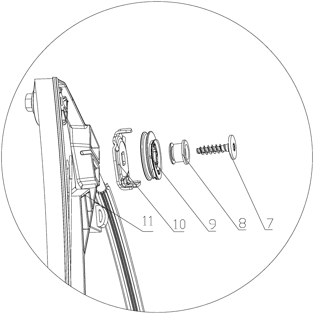
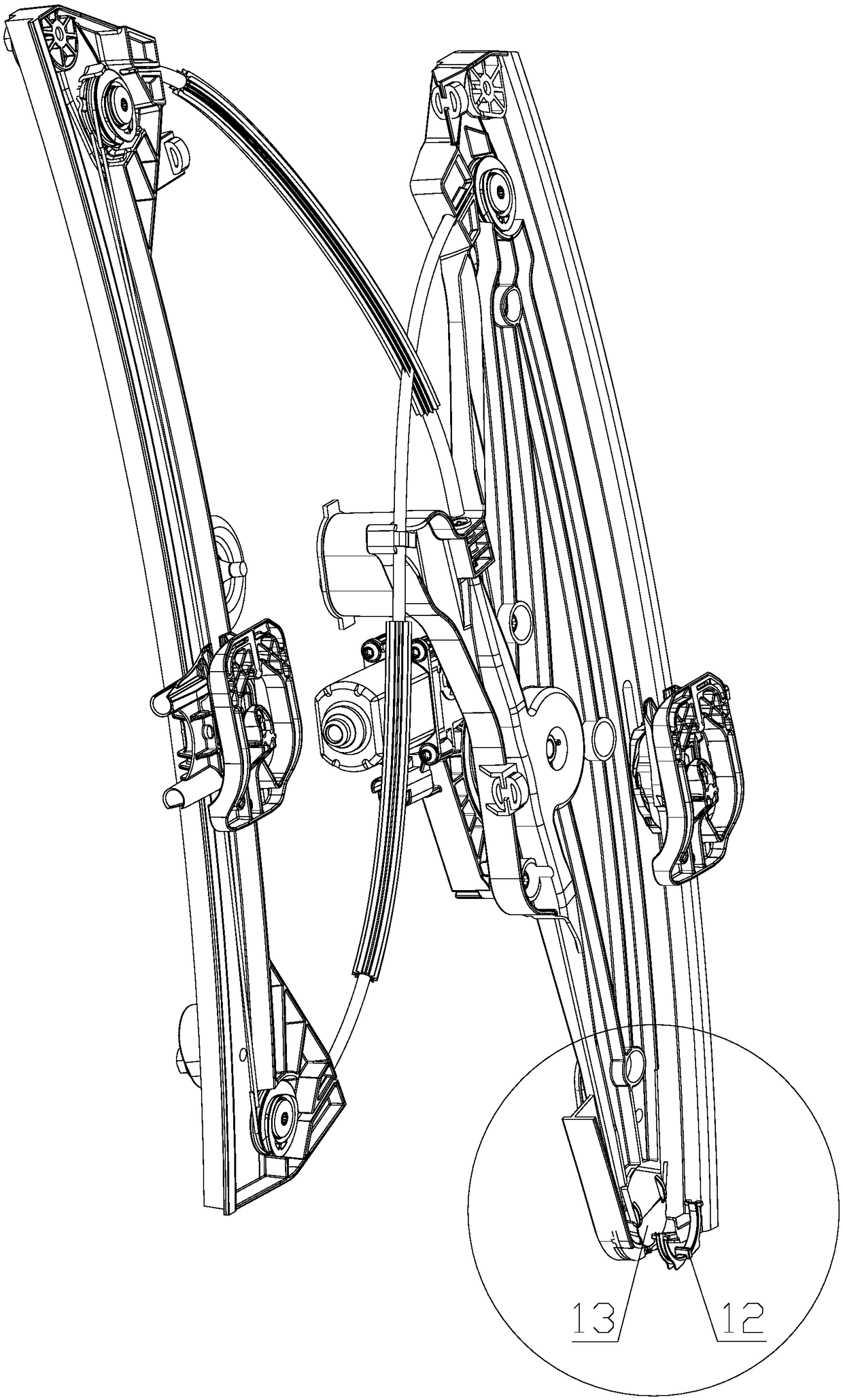
technical field [0001] The invention relates to the technical field of guide rail lifter pulleys, in particular to a pulley connection structure used on a guide rail lifter and the formed guide rail lifter. Background technique [0002] Such as figure 1 , figure 2 As shown, the upper guide structure of the traditional plastic guide rail glass regulator includes a self-tapping screw B7, a guide wheel shaft 8, a guide wheel 9 and a guide wheel bracket 10, the guide wheel bracket 10 is arranged in parallel with the guide wheel 9, and the plastic guide rail glass regulator has Guide rail, the guide rail includes upper guide rail 11 and lower guide rail 13, the guide wheel shaft 8 passes through the guide wheel 9 in turn, the guide wheel bracket 10 is installed on the upper guide rail 11 of the plastic guide rail glass regulator, and the self-tapping screw B7 passes through the guide wheel shaft 8 in turn , guide wheel 9, guide wheel support 10 are fixed on the top guide rail ...

Claims


Application Information

Patent Timeline
Patent Type & Authority Applications(China)
IPC IPC(8): E05F11/48
CPCE05F11/481E05Y2900/55
Inventor 秦志刚李贤龙黄伟吴昶刘剑王浩胡永康姚志雄
Owner 东风博泽汽车系统有限公司
Learn More