Outflow constant method and structure

A constant structure and flow channel technology, applied in the direction of flow control using electrical devices, can solve the problems of inaccurate flow control, affecting the effect of use, unstable performance, etc., to achieve a reasonable overall structure design, ensure the effect of stable flow, Improve the effect of energy dissipation

Pending Publication Date: 2019-02-12
NORTH CHINA UNIV OF WATER RESOURCES & ELECTRIC POWER
View PDF5 Cites 3 Cited by
  • Summary
  • Abstract
  • Description
  • Claims
  • Application Information

AI Technical Summary

Problems solved by technology

[0006] The flow regulator in the above comparative document drives the moving parts through elastic materials (silicone sheet, spring, etc.). Change the size of the end face of the...

Method used


Image

  • Outflow constant method and structure
  • Outflow constant method and structure
  • Outflow constant method and structure

Examples


Embodiment Construction

[0043] In order to make the purpose, technical features and technical effects of the technical solution of the present invention more clear, the exemplary solutions of the embodiments of the present invention will be clearly and completely described below in conjunction with the drawings of specific embodiments of the present invention. Apparently, the described embodiments are some, not all, embodiments of the present invention. Based on the described embodiments of the present invention, all other embodiments obtained by persons of ordinary skill in the art without creative efforts shall fall within the protection scope of the present invention.

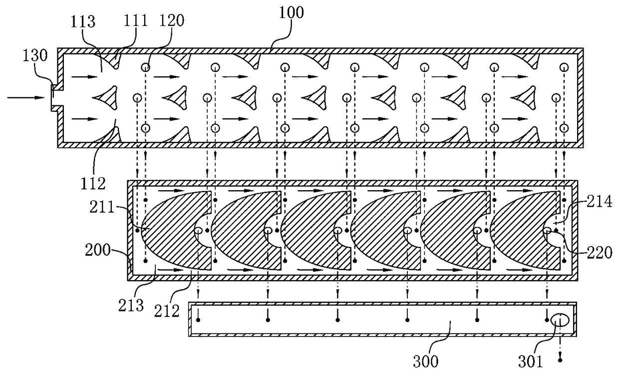
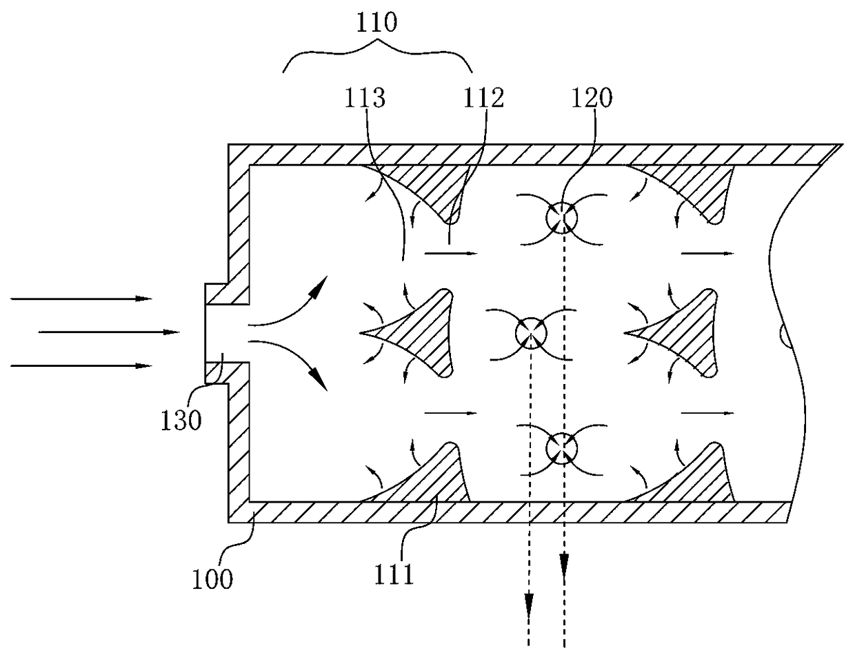
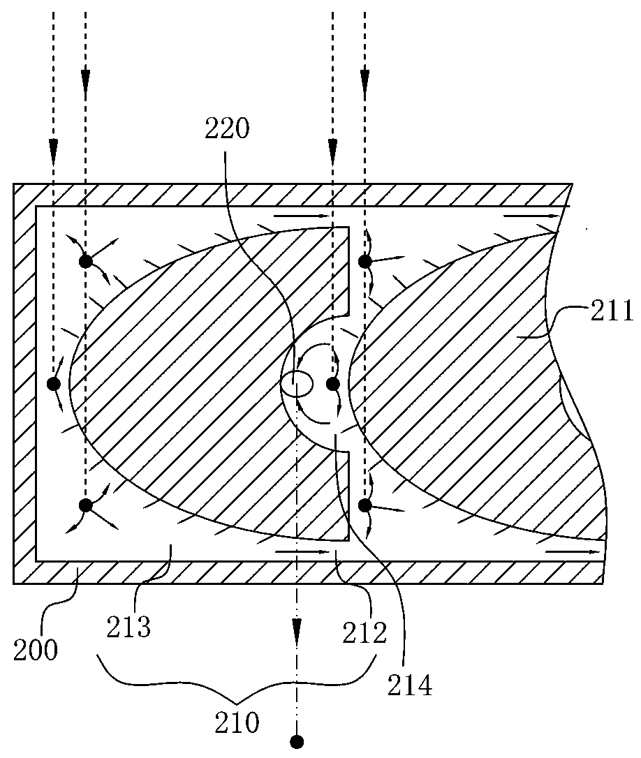
[0044] see Figure 1-Figure 6, a constant outflow structure of the present invention, comprising an upper planar flow channel 100, a lower planar flow channel 200, and an outlet flow channel 300, which are sequentially stacked, and one end of the upper planar flow channel 100 is provided with a water inlet 130, and The top of the ...


PUM


Abstract

The invention belongs to the technology field of irrigation. The outflow constant structure comprises: an upper plane channel, wherein a plurality of primary energy dissipating units are arranged in sequence inside the upper plane channel and a water inlet is arranged at the front end of the upper planar channel; a lower plane channel, wherein a plurality of secondary energy dissipating units arearranged in sequence inside the lower plane channel, a plurality of primary energy dissipating units are respectively arranged corresponding to the plurality of the secondary energy dissipating units,and corresponding communication holes are arranged between the corresponding primary energy dissipating units and the secondary energy dissipating units; and an outlet channel, wherein each of the secondary energy dissipating units is connected to the outlet channel through an outlet and a constant flow port is arranged on the outlet channel. The invention further discloses an outflow constant method. The overall structure of the outflow constant structure has no moving parts, the energy dissipating path is automatically selected according to the water inlet pressure through the four-dimensional energy dissipation, thereby realizing constant flow and constant pressure on the outlet.

Description

technical field [0001] The invention belongs to the technical field of irrigation, and in particular relates to a method and structure for constant outflow. Background technique [0002] Outflow stability is an important method to achieve irrigation uniformity. The main function of the flow regulator is to stabilize the flow, a device that maintains a relatively stable outflow under different inlet pressures. It can automatically adjust the flow through the regulator in a relatively stable range according to the pressure inside the pipe. For example, adding a "flow regulator" (commonly referred to as "flow regulator" and "flow regulator" at the capillary inlet) can solve this problem well, so the capillary flow regulator is used more more and more popular. Strong pressure compensation, especially suitable for undulating terrain, uneven system pressure and long capillary. [0003] Combining the flow regulator with the dripper is a compensating dripper, which uses the press...

Claims


Application Information

Patent Timeline
IPC IPC(8): G05D7/06
CPCG05D7/06
Inventor 仵峰刘少波宰松梅仵迪刘焕
Owner NORTH CHINA UNIV OF WATER RESOURCES & ELECTRIC POWER
Why Eureka
Try Eureka