
Computer USB (Universal Serial Bus) interface splitter and method

A technology of USB interface and splitter, which is applied in the direction of line/collector components, computer peripheral equipment connectors, circuits, etc., which can solve the problems of inconvenient plugging and unplugging USB interfaces, idle waste of USB interfaces, and inability to adjust the orientation at will. , to achieve the effect of compact structure, solving idle waste and high adjustment

Pending Publication Date: 2019-02-12
大连鑫鑫创世科技发展有限公司
View PDF15 Cites 0 Cited by
  • Summary
  • Abstract
  • Description
  • Claims
  • Application Information

AI Technical Summary

Problems solved by technology

[0003] The wide application of USB devices makes it necessary to often plug and unplug the USB interface of the computer, and the USB interface of the computer is often at the rear of the host, which makes it very inconvenient to plug and unplug. For this reason, the host computer is often provided with a front-mounted USB interface. And because the host is generally placed on the lower part of the computer desk, it is inconvenient to bend over to plug in and out the USB interface, so the USB hub came into being
[0004] The position of the existing USB interface splitter cannot be adjusted arbitrarily, and the adjustable adaptability is poor, and one USB connector can only be used by one computer, and there is a situation where the USB interface is idle and wasted

Method used


Image

  • Computer USB (Universal Serial Bus) interface splitter and method
  • Computer USB (Universal Serial Bus) interface splitter and method
  • Computer USB (Universal Serial Bus) interface splitter and method

Examples


Embodiment 1

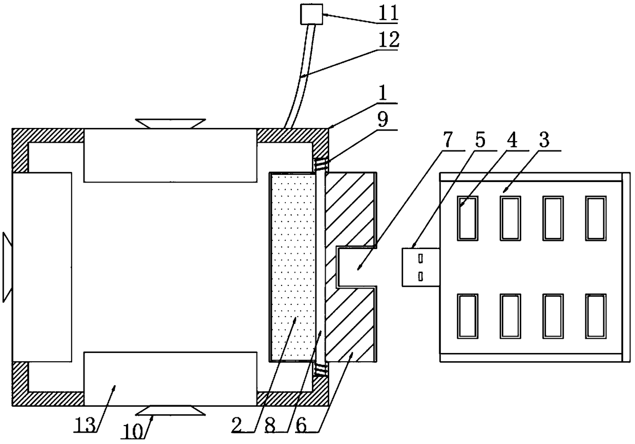
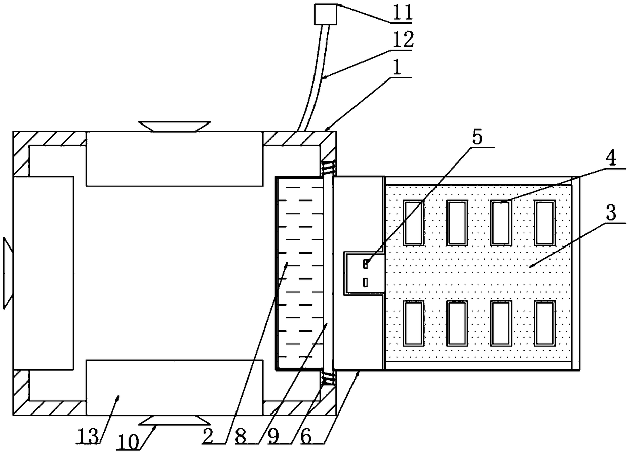
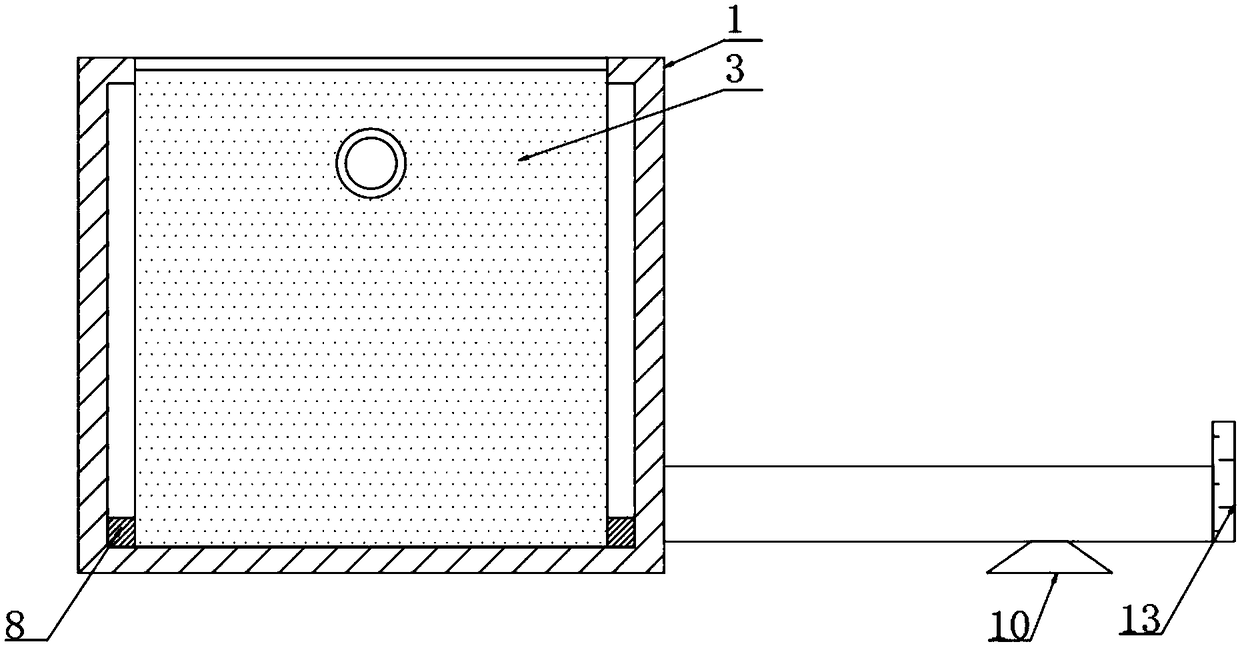
[0026] The present invention provides such Figure 1-3 The shown computer USB interface splitter includes a housing 1, a groove 2 is arranged on the outside of the housing 1, and a connecting plate 3 is arranged inside the groove 2, and the connecting plate 3 is close to the housing 1 One side of the connecting plate 3 is provided with a first USB interface 4, the bottom of the connecting plate 3 is provided with a first USB connector 5, the bottom of the first USB connector 5 is provided with a support block 6, and the middle part of the support block 6 is provided with a second USB Interface 7, the connection between the bottom of the support block 6 and the housing 1 is provided with a rotating shaft 8, both ends of the rotating shaft 8 are provided with torsion springs 9, and the side of the connecting plate 3 away from the housing 1 is provided with a suction cup 10. A second USB connector 11 is provided outside the housing 1 .

[0027] Further, in the above technical so...

Embodiment 2

[0036] A computer USB interface splitting method, including the computer USB interface splitter, also includes the following steps:

[0037] S1: the first USB connector 5 provided at the bottom of the connection board 3 is plugged into the second USB interface 7 provided at the middle of the support block 6;

[0038] S2: fixing the connecting plate 3 and the supporting block 6 together;

[0039] S3: Open the connecting plate 3 by pulling the connecting plate 3;

[0040] S4: Separate the support block 6 from the connection board 3 and split it into multiple separate USB splitters for use by multiple computers.


PUM


Abstract

The invention discloses a computer USB interface deconcentrator and method. The computer USB interface deconcentrator comprises a shell, wherein a groove is formed in the outer side of the shell; a connecting plate is arranged inside the groove; a first USB interface is arranged on the side, close to the shell, of the connecting plate; a first USB connector is arranged at the bottom of the connecting plate; a supporting block is arranged at the bottom of the first USB connector; a second USB interface is arranged at the middle part of the supporting block; a rotating shaft is arranged at a joint of the bottom of the supporting block and the shell; torsion springs are arranged at two ends of the rotating shaft; a suction disk is arranged on the side, away from the shell, of the connecting plate; and a second USB connector is arranged on the outer side of the shell. By the arrangement of the connecting plate and the supporting block, as multiple connecting plates are arranged on the surface of the shell, the connecting plates can be opened in different directions from the shell, and the adjustability is high.

Description

technical field [0001] The invention relates to the technical field of computer accessories, in particular to a computer USB interface splitter and a method thereof. Background technique [0002] The Chinese meaning of USB is "Universal Serial Bus". It is not a new bus standard, but an interface technology applied in the PC field. Since the USBV0.7 version was released on November 11, 1994, the USB version has experienced years of development, and now it has developed into version 2.0, which has become the standard expansion interface in computers at present, and the USB versions can be well compatible. USB uses a 4-pin plug as a standard plug, and all peripherals can be connected in a daisy chain form, up to 127 external devices can be connected without loss of bandwidth. USB needs the support of host hardware, operating system and peripheral hardware to work. The current motherboard generally adopts a control chipset that supports USB functions. There is also a USB inte...

Claims


Application Information

Patent Timeline
Patent Type & Authority Applications(China)
IPC IPC(8): H01R13/502H01R13/508H01R13/52H01R13/73H01R24/00H01R25/00H01R31/00H01R43/00H01R43/26
CPCH01R13/502H01R13/508H01R13/52H01R13/73H01R24/00H01R25/006H01R31/005H01R43/00H01R43/26H01R2201/06
Inventor 白涛安鑫鑫
Owner 大连鑫鑫创世科技发展有限公司
Learn More