Environment-friendly electrical equipment used in factory and using method of electrical equipment

An electrical equipment and environmental protection technology, applied in the field of environmental protection electrical equipment for factories, can solve the problem of time and labor for scrap recycling, and achieve the effects of saving water and energy, reducing the amount of dust disposal, and improving collection efficiency.

Active Publication Date: 2019-02-15
CHAOHU JINHUI AUTOMATIC CONTROL EQUIP
View PDF6 Cites 2 Cited by
  • Summary
  • Abstract
  • Description
  • Claims
  • Application Information

AI Technical Summary

Problems solved by technology

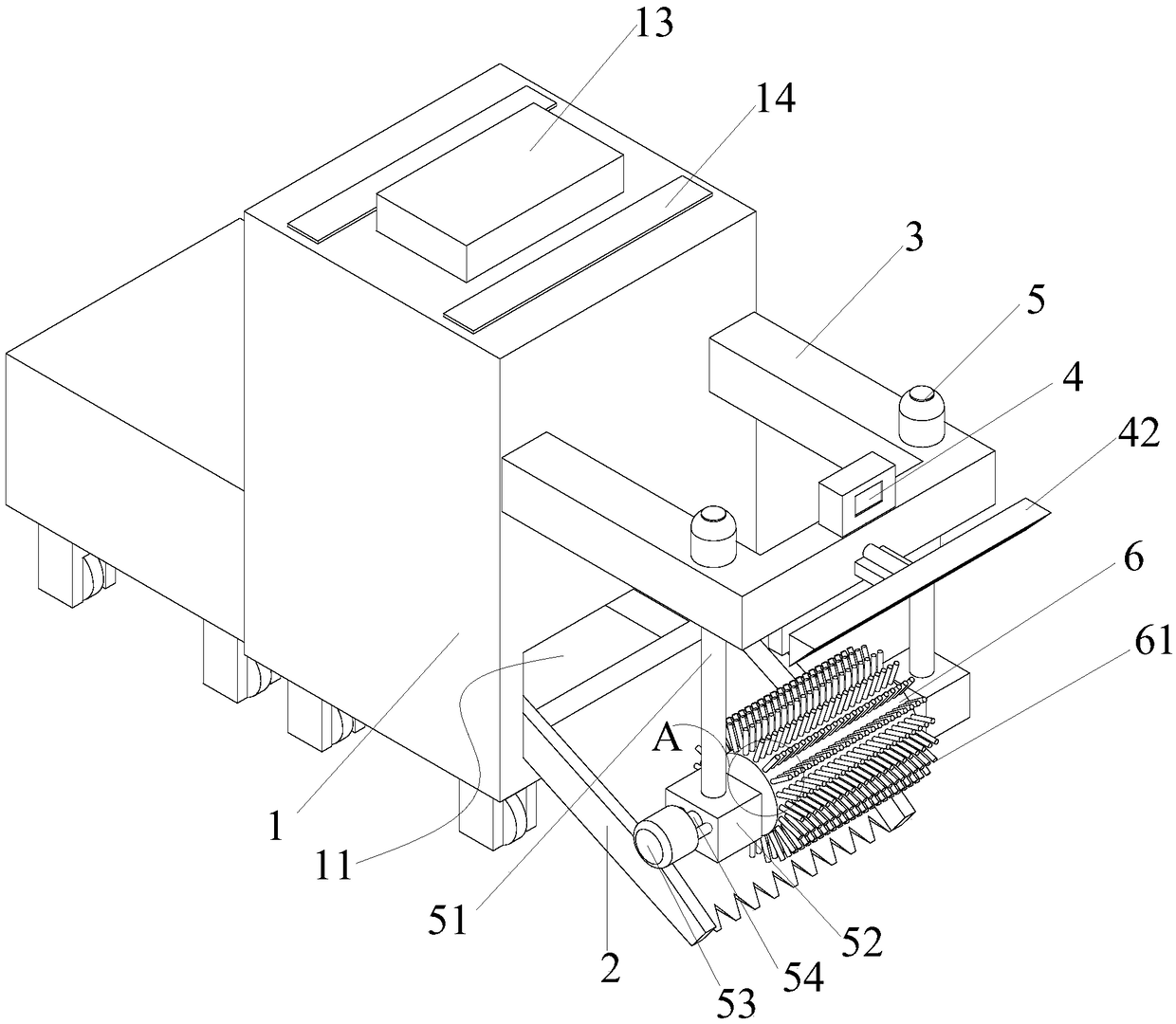
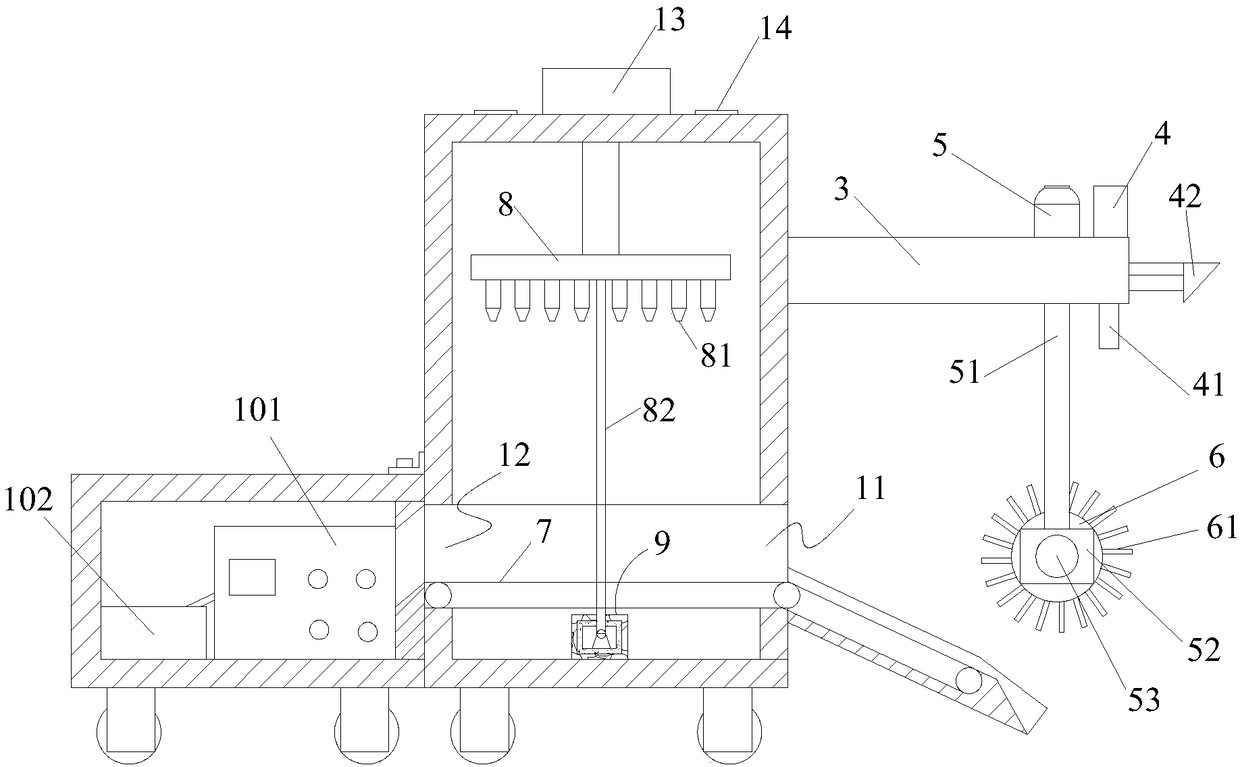
[0004] The object of the present invention is to provide a kind of environment-friendly electrical equipment for factories, by setting up a shovel bucket, a cleaning roller, a crawler belt and a material storage box, and cleaning rollers, the debris on the road surface is cleaned to the shovel bucket, and then passed through the crawler belt. Recycling the crushed materials into the storage box solves the problem of time-consuming and laborious recycling of the crushed materials, and achieves the purpose of energy saving and environmental protection in the factory

Method used


Image

  • Environment-friendly electrical equipment used in factory and using method of electrical equipment
  • Environment-friendly electrical equipment used in factory and using method of electrical equipment
  • Environment-friendly electrical equipment used in factory and using method of electrical equipment

Examples


Embodiment Construction

[0041] The following will clearly and completely describe the technical solutions in the embodiments of the present invention with reference to the accompanying drawings in the embodiments of the present invention. Obviously, the described embodiments are only some, not all, embodiments of the present invention. Based on the embodiments of the present invention, all other embodiments obtained by persons of ordinary skill in the art without creative efforts fall within the protection scope of the present invention.

[0042] In describing the present invention, it should be understood that the terms "upper", "lower", "middle", "wall", "inner", "outer", "end", "side" etc. indicate orientation or positional relationship , are only for the convenience of describing the present invention and simplifying the description, but do not indicate or imply that the components or elements referred to must have a specific orientation, be constructed and operated in a specific orientation, and ...


PUM


Abstract

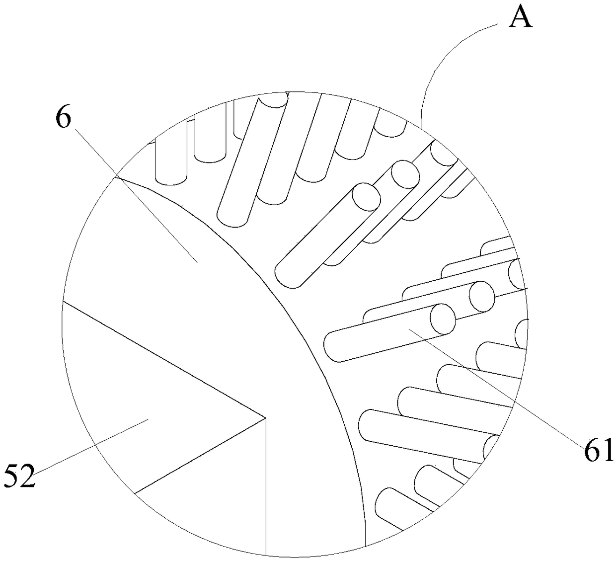
The invention relates to the technical field of electrical equipment, and discloses environment-friendly electrical equipment used in a factory and a using method of the electrical equipment. The electrical equipment comprises a cleaning machine, a material inlet and a material outlet are formed in the cleaning machine, the lower end of the material inlet is fixedly provided with a shovel plate bucket, the cleaning machine is provided with two telescoping air cylinders, and the telescoping air cylinders are connected with installation blocks respectively. A cleaning roller is rotationally connected between the two installation blocks, a plurality of bristles are arranged on the circumferential side of the cleaning roller in an array, the cleaning machine is provided with a track, one end of the track is rotationally installed in the shovel plate bucket, and the other end of the track is rotationally connected to the material outlet. A spraying pipe is fixedly installed on the inner wall at the upper end of the cleaning machine, and the cleaning machine is fixedly connected with a material storage box. By arranging the shovel plate bucket, the cleaning roller, the track and the material storage box, debris on the road surface is cleaned away through the cleaning roller into the shovel plate bucket, the debris is recovered into the material storage box through the track, the problem the recovery of the debris wastes time and labor is solved, and the aims that the factory saves energy and is environmentally friendly are achieved.

Description

technical field [0001] The invention belongs to the technical field of electrical equipment, and in particular relates to an environment-friendly electrical equipment used in a factory and a usage method thereof. Background technique [0002] The widespread use of electrical equipment has gradually improved people's daily life and liberated people's labor force. People can design electrical equipment and devices that meet the needs to meet people's growing needs. [0003] For example, with the development of society and the gradual strengthening of people's awareness of environmental protection, the collection and cleaning of debris dropped on the ground during factory processing, production and transportation has become an important task for factories to recycle and make full use of these debris in a timely manner , not only can maintain the cleanliness of the workshop, but also can save production costs, and now usually a large number of manual cleaning is organized by the...

Claims


Application Information

Patent Timeline
Patent Type & Authority Applications(China)
IPC IPC(8): A47L11/24A47L11/40
CPCA47L11/24A47L11/40A47L11/4013A47L11/4027A47L11/4041A47L11/4088
Inventor 何来传
Owner CHAOHU JINHUI AUTOMATIC CONTROL EQUIP
Why Eureka
Try Eureka