Dust remover capable of realizing intelligent discharging

A dust collector, intelligent technology, applied in the direction of chemical instruments and methods, dispersed particle separation, combined devices, etc., can solve the problems that maintenance personnel cannot judge the damage location, increase maintenance difficulty and time, reduce dust removal effect, etc., and achieve improved dust removal The effect of saving maintenance time and reducing the difficulty of maintenance

Inactive Publication Date: 2019-02-15
广东嗨学云教育科技有限公司
View PDF7 Cites 3 Cited by
  • Summary
  • Abstract
  • Description
  • Claims
  • Application Information

AI Technical Summary

Problems solved by technology

[0003] The present invention provides a dust remover capable of intelligent blanking, which can effectively solve the common dust removal device proposed in the above-mentioned background technology. Dust removal is carried out through the same dust removal room. Due to the continuous diffusion of gas in the dust removal room, the dust in different areas of the room Gas filtration and purification effects are different, thereby reducing the dust removal effect, and the common dust removal device has a simple feeding structure, and the filtered dust is exported through a single ash hopper. When a large amount of dust is filtered inside the device, condensation is often caused by the untimely dust falling The outlet of the ash hopper is blocked in blocks, and the exported dust is relatively light, so it is easy to enter the environment again during post-processing, causing secondary pollution. When the device is damaged, maintenance personnel cannot judge the location of the damage because they cannot observe the inside of the device in time , thus increasing the maintenance difficulty and maintenance time and other issues

Method used


Image

  • Dust remover capable of realizing intelligent discharging
  • Dust remover capable of realizing intelligent discharging
  • Dust remover capable of realizing intelligent discharging

Examples


Embodiment

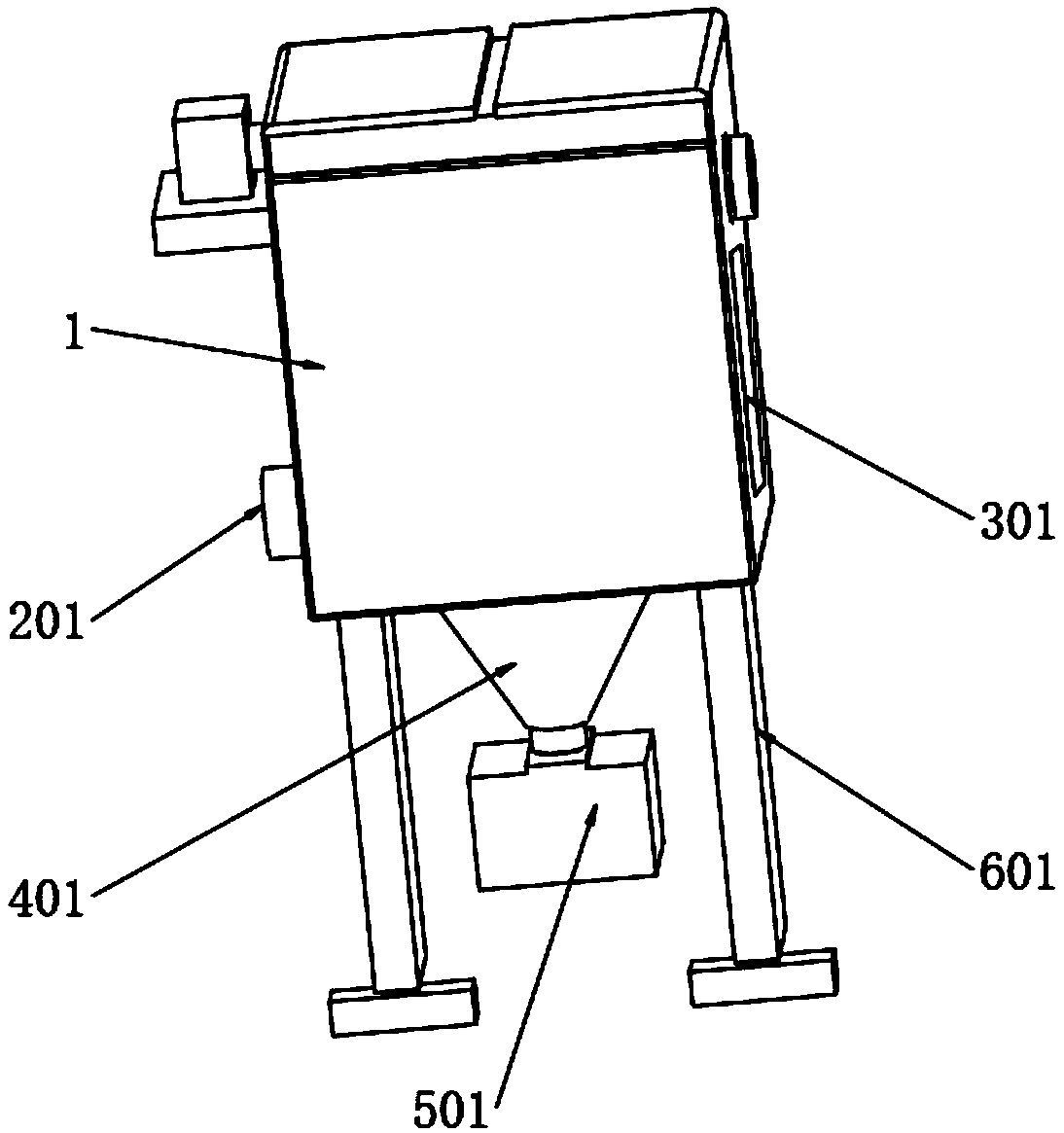
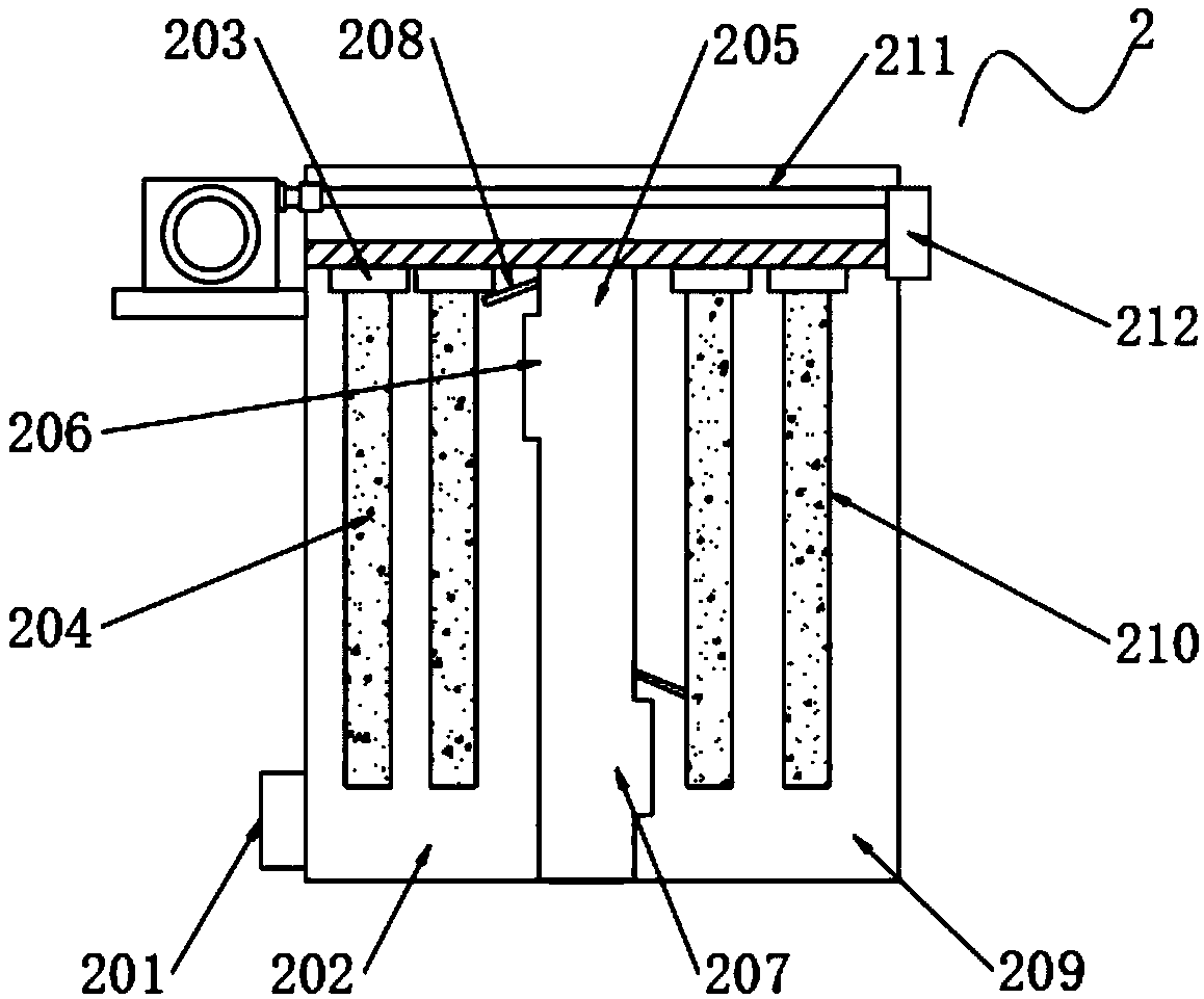
[0030] Example: such as Figure 1-6As shown, the present invention provides a technical solution, a dust collector capable of intelligent blanking, including a dust removal box 1, a dust removal assembly 2 is installed inside the dust removal box 1, and the dust removal assembly 2 includes an air inlet pipe 201, a first dust removal chamber 202 , Venturi tube 203, first dust filter bag 204, connecting channel 205, air inlet 206, air outlet 207, air deflector 208, second dust chamber 209, second dust filter bag 210, compressed air pipe 211 and exhaust Air duct 212, the lower end of one side of the dust removal box 1 is equipped with an air inlet pipe 201, the side of the air inlet pipe 201 is installed with a first dust removal chamber 202, and the top of the first dust removal chamber 202 is equipped with a Venturi tube 203, and the Venturi tube The first dust removal filter bag 204 is installed on the outside of 203, and a connecting channel 205 is installed on one side of th...


PUM


Abstract

The invention discloses a dust remover capable of realizing intelligent discharging. The dust remover comprises a dust removal box, wherein a dust removal assembly is mounted in the dust removal box,and a discharging assembly is mounted at the lower end of the dust removal assembly. The dust remover is scientific and reasonable in structure and safe and convenient to use; the dust removal assembly is arranged, primary dust removal work is performed on the air under the action of a first dust removal chamber, a venturi tube and a first dust removal filter bag; further dust removal is performedon the air under the action of a connecting channel, a second dust removal chamber and a second dust removal filter bag, and thus, the dust removal effect of the device is improved; the discharging assembly is arranged, dust removed from the dust removal chambers is lead out conveniently under the action of an ash hopper and an ash outlet; a vibrating plate is beaten continuously and convenientlyunder the action of a vibrating spring, the vibrating plate, a power wheel and a bulge, so that the vibrating plate vibrates continuously under the elastic action of the vibrating spring, dust is vibrated away, dropping of the dust is accelerated, blockage due to accumulation of dust at the outlet is avoided, and the dust remover is convenient to use.

Description

technical field [0001] The invention relates to the technical field of dust collectors, in particular to a dust collector capable of intelligent blanking. Background technique [0002] The dust collector is a device that separates dust from the flue gas. The performance of the dust collector is expressed by the amount of gas that can be processed, the resistance loss when the gas passes through the dust collector, and the dust removal efficiency. There are many types of dust collectors, including filter dust collectors. Bag dust collectors and particle layer dust collectors, electrostatic precipitators, magnetic dust collectors, dry dust collectors, semi-dry dust collectors, wet dust collectors, electric bag composite dust collectors and bag dust collectors are more commonly used in industry now. The electric bag composite dust collector is installed in a box, with a short electric field installed at the front end and a filter bag field installed at the rear end. The smoke a...

Claims


Application Information

Patent Timeline
Patent Type & Authority Applications(China)
IPC IPC(8): B01D50/00
CPCB01D50/60
Inventor 王强
Owner 广东嗨学云教育科技有限公司
Why Eureka
Try Eureka