Novel electrolytic milling method and device for machined gap through electrolyte wall-attaching direct spraying

A technology of machining gap and milling device, which is applied in the field of electrolytic milling method and device for direct injection machining gap of electrolyte solution, can solve the problems of inability to obtain high-speed, large-flow electrolyte, large kinetic energy loss, and reduced machining efficiency, etc. Achieve the effect of improving processing efficiency and processing stability, reducing kinetic energy loss and improving processing efficiency

Active Publication Date: 2019-02-15
GUANGDONG UNIV OF TECH
View PDF5 Cites 3 Cited by
  • Summary
  • Abstract
  • Description
  • Claims
  • Application Information

AI Technical Summary

Problems solved by technology

In the electrolytic milling device and method using external spray liquid supply, the electrolyte also enters the processing area through a turning point, or enters the front processing area from the rear of the feeding direction. In both ways, the working fluid is not directly sprayed into the processing area. The loss of kinetic energy during the movement is huge, and the processing area cannot obtain high-speed and large-flow electrolyte, which can only reduce the processing efficiency to ensure the stability of the processing process

Method used


Image

  • Novel electrolytic milling method and device for machined gap through electrolyte wall-attaching direct spraying
  • Novel electrolytic milling method and device for machined gap through electrolyte wall-attaching direct spraying
  • Novel electrolytic milling method and device for machined gap through electrolyte wall-attaching direct spraying

Examples


Embodiment

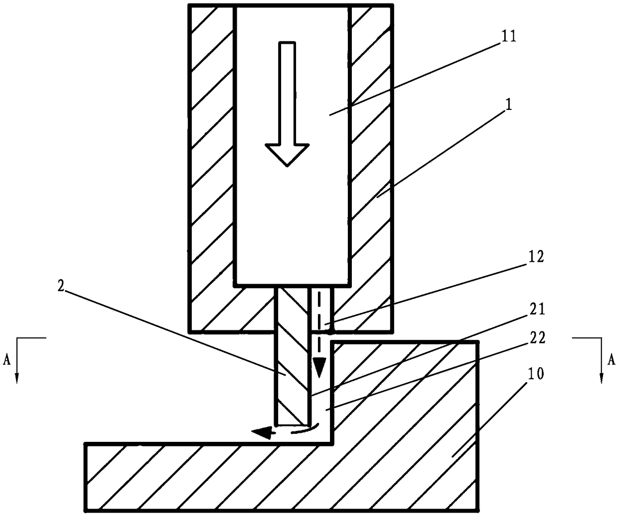
[0029] see Figure 1 to Figure 4 , the present embodiment relates to a new electrolytic milling method for electrolytic milling of gaps through wall-mounted direct injection, including the following steps:

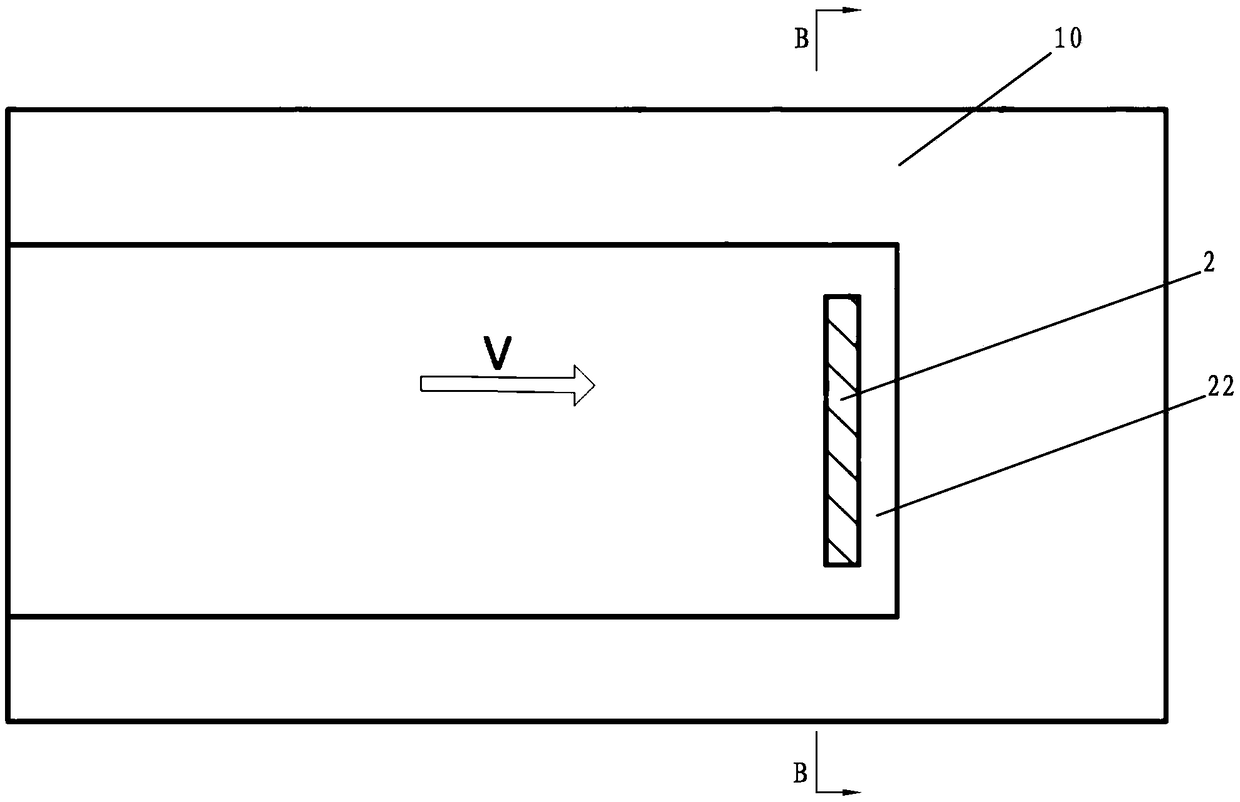
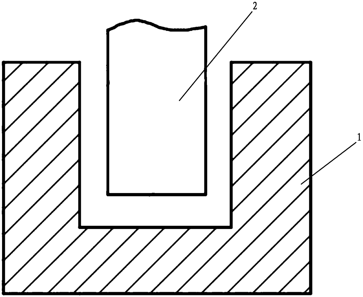
[0030] Step 1, the cathode processing section 2 processes the workpiece 10 with its front wall surface 21 in the feeding direction;

[0031] Step 2, the electrolyte is sprayed onto the front wall 21 of the cathode processing section 2 from the liquid injection port 12 in a direction parallel to the front wall 21 of the cathode processing section 2, and the electrolyte is sprayed along the front wall 21 of the cathode processing section 2 to the cathode processing In the processing area 22 between the front end face of the segment 2 and the workpiece 10;

[0032] Step 3: The electrolyte entering the processing area 22 between the front wall 21 of the cathode processing section 2 and the workpiece 10 scours and takes away the electrolytic products generated during processin...


PUM

PropertyMeasurementUnit
widthaaaaaaaaaa

Abstract

The invention discloses an electrolytic milling method for a machined gap through electrolyte wall-attaching direct spraying. The front wall face of the front end in the feeding direction of a cathodemachining section is used for machining a workpiece, an electrolyte comes out from a liquid spraying opening in the bottom of a cathode body on the upper part of the cathode machining section and isdirectly sprayed to enter a machining area in the mode of closely attaching a cathode machining face, namely wall-attaching direct spraying, and thus the kinetic energy loss caused by electrolyte steering is avoided. The liquid supplying mode is extremely simple, compared with ordinary metal milling, milling can be conducted more flexibly, the high-speed and large-flow electrolyte can enter the machining area at the minimum loss, and thus the electrolytic machining speed is increased in a multiplied mode. The invention further discloses an electrolytic milling device implementing the electrolytic milling method, the electrolytic milling device comprises the cathode body, and the cathode machining section is arranged at the lower end of the cathode body; feeding is conducted according to aset trajectory; the inner side face of the liquid spraying opening in the lower end face of a cathode clamping body and the front wall face of the cathode machining section are located on the same plane, and the electrolyte sprayed from the liquid spraying opening is directly sprayed to enter the machining area in the mode of closely attaching the front wall face of the cathode machining section.

Description

technical field [0001] The invention relates to an electrolytic milling method and a device thereof, in particular to an electrolytic milling method and a device thereof in which an electrolyte solution is adhered to a wall and directly sprayed to process gaps. Background technique [0002] Electrolytic milling uses a simple cathode to form the workpiece surface through the envelope surface of the cathode movement trajectory, which has the advantages of large flexibility and short preparation period. The existing liquid supply methods for electrolytic milling are mainly divided into internal spray liquid supply and external spray liquid supply. For the electrolytic milling device and method of internal spray liquid supply, the electrolyte enters the processing area after turning 90° or at a certain angle after coming out of the nozzle. In the electrolytic milling device and method using external spray liquid supply, the electrolyte also enters the processing area through a ...

Claims


Application Information

Patent Timeline
Patent Type & Authority Applications(China)
IPC IPC(8): B23H5/06
CPCB23H5/06
Inventor 张传运张永俊尧佳路陈晓磊张琮源刘桂贤
Owner GUANGDONG UNIV OF TECH
Why Eureka
Try Eureka