
Laser marking machine

A laser marking machine and laser marking technology, applied in the field of laser marking machines, can solve problems such as unstable laser beam output and affecting the marking effect of marking machines, and achieve stable operation, high processing efficiency, and high marking efficiency. high quality effect

Pending Publication Date: 2019-02-15
IKD CO LTD
View PDF0 Cites 3 Cited by
  • Summary
  • Abstract
  • Description
  • Claims
  • Application Information

AI Technical Summary

Problems solved by technology

[0003] In the working state, the temperature generated by the laser generator of the laser marking equipment is high, and the laser beam output of the laser generator will be unstable under high temperature conditions, which will affect the marking effect of the marking machine

Method used


Image

  • Laser marking machine
  • Laser marking machine
  • Laser marking machine

Examples


Embodiment Construction

[0027] The following descriptions are only preferred embodiments of the present invention, and therefore do not limit the protection scope of the present invention.

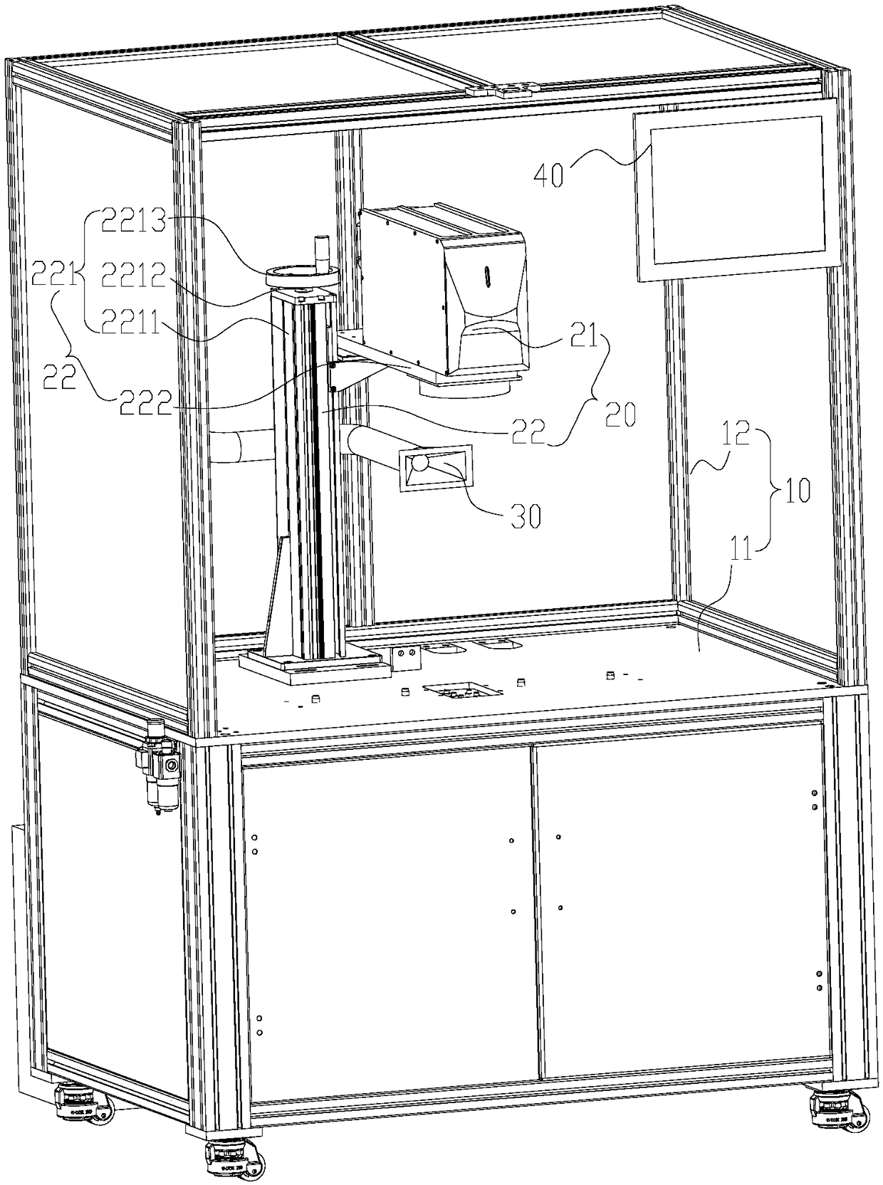
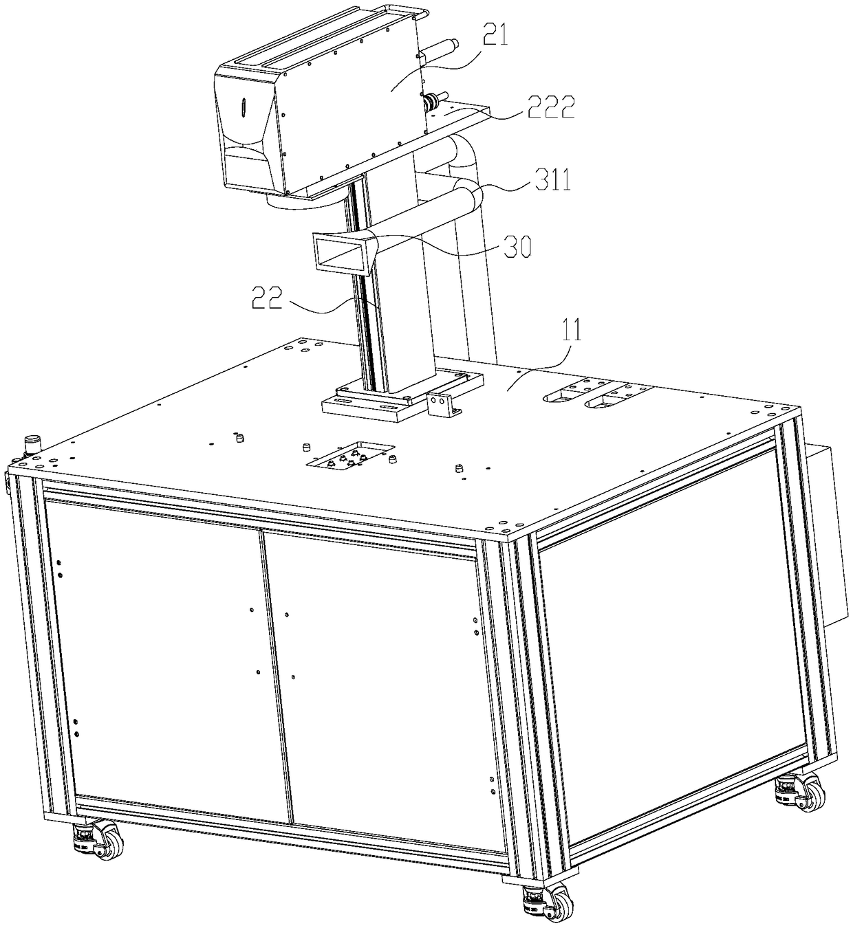
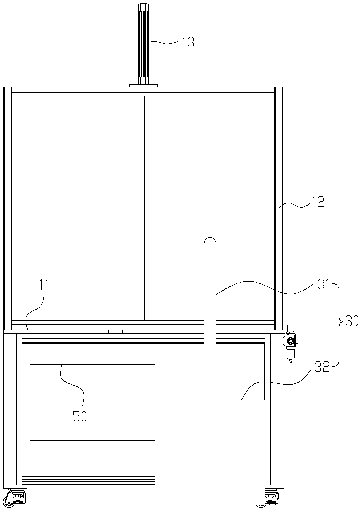
[0028] Examples, see Figure 1 to Figure 7 As shown: the laser marking machine includes a frame 10, a control assembly 40 and a temperature adjustment assembly 50 installed in the frame 10, a laser marking device 20 and a fixture assembly 70 assembled in the frame 10, the control assembly 40 and the laser marking The marking device 20 and the fixture assembly 70 are electrically connected. The frame 10 includes a workbench 11 and a processing cover 12 assembled on the workbench 11. The processing cover 12 has a closed processing space. The laser marking device 20 and the fixture assembly 70 are installed on the workbench 11 and are located in the processing space. The laser marking device 20 is processing the workpiece 80 mounted on the fixture assembly 70 , and the temperature adjustment assembly 50 is used to ...


PUM


Abstract

The invention discloses a laser marking machine. The laser marking machine comprises a rack, a control assembly, a temperature adjusting assembly, a laser marking device and a clamp assembly, whereinthe control assembly and the temperature adjusting assembly are mounted on the rack, and the laser marking device and the clamp assembly are assembled in the rack; the control assembly is electricallyconnected with the laser marking device and the clamp assembly, and the rack comprises a worktable and a machining cover assembled to the worktable; and the machining cover is provided with a closedmachining space, and the laser marking device and the clamp assembly are mounted on the worktable and both located in the machining space. When the laser marking device machines a workpiece assembledto the clamp assembly, the temperature adjusting assembly is used for adjusting the temperature of the machining space to enable the temperature in the machining space to be within the preset range; the laser marking machine is equipped with the temperature adjusting assembly, so that the laser marking device is within the preset temperature range; and the clamp assembly clamps the preset positionof the workpiece so that the laser marking device can accurately conduct marking, the workpiece can be quickly replaced, and thus the machining efficiency is high.

Description

technical field [0001] The invention relates to the technical field of laser marking, in particular to a laser marking machine. Background technique [0002] Laser marking equipment uses laser beams to mark permanent marks on the surface of various substances. It exposes deep substances through the evaporation of surface substances, thereby engraving exquisite patterns, trademarks and characters on the surface of the workpiece. For example, laser marking equipment is used in electronic components, integrated circuits (IC), electrical appliances, mobile communications, hardware products, tool accessories, precision instruments, glasses clocks, jewelry, auto parts, plastic buttons, building materials, PVC pipes The surface is laser marked. [0003] In the working state, the temperature generated by the laser generator of the laser marking equipment is high, and the laser beam output of the laser generator will be unstable under high temperature conditions, which will affect t...

Claims


Application Information

Patent Timeline
IPC IPC(8): B23K26/362B23K26/08B23K26/70B23K37/04B23K26/16
CPCB23K26/0869B23K26/16B23K26/361B23K26/362B23K26/702B23K26/703B23K37/0443
Inventor 何盛华柳红艳余坤何晓衡高鹏飞
Owner IKD CO LTD
Learn More