Bending moment suspension driven by motor

A technology of motor drive and suspension, applied in the field of torque variable suspension, which can solve the problems affecting suspension sensitivity, weak torque output and battery life, and affecting vehicle battery life, etc., to achieve easy disassembly and adjustment, reduce micro vibration, reduce The effect of degrees of freedom

Active Publication Date: 2019-02-15
汤在英
View PDF7 Cites 0 Cited by
  • Summary
  • Abstract
  • Description
  • Claims
  • Application Information

AI Technical Summary

Problems solved by technology

[0002] Because electric vehicles are driven by motors, their torque output and endurance are weaker than those of internal combustion engines, so they require other components in the car to be lightweight to ensure their endurance. The suspension of the car mainly uses large steel springs and Larger damping rods realize elastic support and shock absorption support. Steel springs and damping rods are generally made of steel, which is heavy and easily affects the endurance of the car; therefore, it is necessary to propose a suspension with relatively low weight and stable performance. The shock absorbing mechanism of the frame; the existing electromagnetic suspension driven by a linear motor mainly relies on a large linear motor installed on the suspension link to replace the spring and the damping rod for shock absorption, but because the linear motor is installed on the suspension Above, the relatively heavy linear motor will affect the sensitivity of the suspension and steering to a certain extent, affect the driving experience, and also affect the battery life

Method used


Image

  • Bending moment suspension driven by motor
  • Bending moment suspension driven by motor
  • Bending moment suspension driven by motor

Examples


Embodiment Construction

[0021] The present invention is described in further detail now in conjunction with accompanying drawing. These drawings are all simplified schematic diagrams, which only illustrate the basic structure of the present invention in a schematic manner, so they only show the configurations related to the present invention.

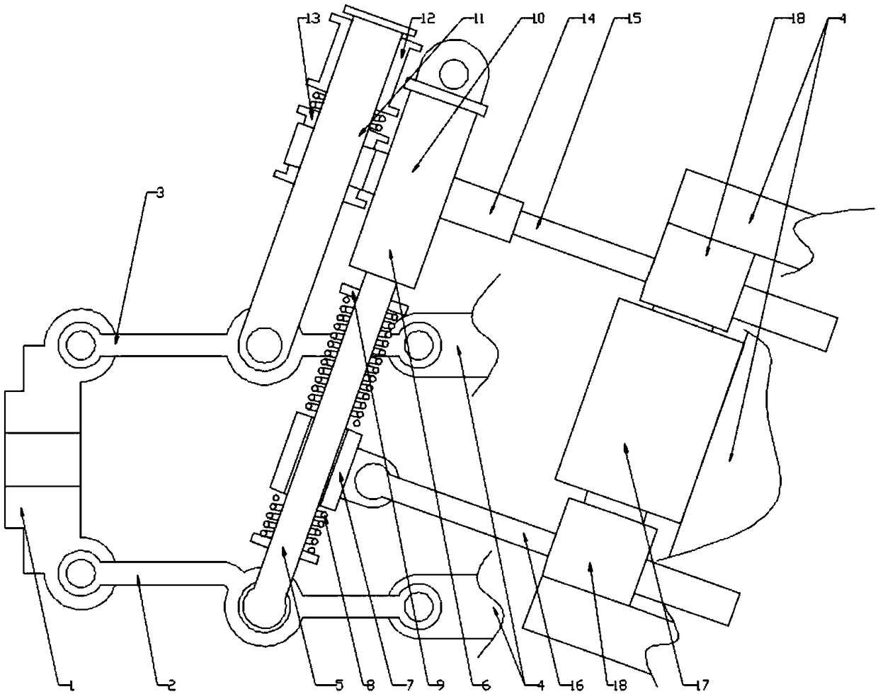
[0022] Such as figure 1 As shown, the present invention is a torque converter suspension driven by a motor, including a steering connecting frame 4, and also includes a connecting rod assembly, a sliding bar assembly and a motor resistance increasing assembly; wherein the connecting rod assembly includes a drive shaft connecting frame 1 , the middle part of the drive shaft connection frame 1 is provided with a drive shaft connection hole 26; the linkage assembly also includes a top link 3 and a bottom link 2, and one end of the top link 3 is rotatably connected to the drive shaft connection frame 1 In the middle, the other end is rotatably connected to the to...


PUM


Abstract

The invention relates to a bending moment suspension driven by a motor. The bending moment suspension driven by the motor comprises a steering connecting frame, a connecting rod assembly, a sliding bar assembly and a motor resistance increasing assembly. The connecting rod assembly comprises a drive shaft connecting frame, wherein a drive shaft connecting hole is formed in the middle part of the drive shaft connecting frame. The connecting rod assembly comprises a top connecting rod and a bottom connecting rod. The sliding bar assembly comprises a bottom sliding bar and a top sliding bar, wherein the bottom sliding bar comprises a telescopic sleeve, and the telescopic sleeve is rotatably connected to the middle part of the bottom connecting rod. The telescopic sleeve is slidably connectedwith a bottom sliding sleeve. The top sliding bar is rotatably connected with the middle part of the top connecting rod, and a supporting sliding sleeve sleeves the top sliding bar. A top sliding sleeve sleeves the middle part of a linear connecting rod. The motor resistance increasing assembly comprises a rotating motor, and steering commutators are separately arranged at two axial ends of a rotating motor. The top sliding sleeve is rotatably connected with a push rod A through a coupling, the end part of the push rod A is connected with the top steering commutator, the bottom sliding sleeveis rotatably connected with a push rod B through the coupling, and the push rod B is connected with the bottom steering commutator.

Description

technical field [0001] The invention relates to a torque-changing suspension driven by a motor, which belongs to the field of electric vehicles. Background technique [0002] Because electric vehicles are driven by motors, their torque output and endurance are weaker than those of internal combustion engines, so they require other components in the car to be lightweight to ensure their endurance. The suspension of the car mainly uses large steel springs and Larger damping rods realize elastic support and shock absorption support. Steel springs and damping rods are generally made of steel, which is heavy and easily affects the endurance of the car; therefore, it is necessary to propose a suspension with relatively low weight and stable performance. The shock absorbing mechanism of the frame; the existing electromagnetic suspension driven by a linear motor mainly relies on a large linear motor installed on the suspension link to replace the spring and the damping rod for shock...

Claims


Application Information

Patent Timeline
Patent Type & Authority Applications(China)
IPC IPC(8): B60G17/015
CPCB60G17/015
Inventor 孙栋
Owner 汤在英
Why Eureka
Try Eureka