Take-up machine

A technology of a wire take-up machine and a wire take-up device is applied in the field of wire take-up machines, which can solve problems such as troublesome disk change, skewed placement, and potential safety hazards, and achieve the effect of ensuring the wire-receiving process, preventing wire breakage, and improving work efficiency.

Active Publication Date: 2019-02-15
WUXI JUYI TONGCHUANG TECH CO LTD
View PDF14 Cites 5 Cited by
  • Summary
  • Abstract
  • Description
  • Claims
  • Application Information

AI Technical Summary

Problems solved by technology

[0003] There are some deficiencies in the wire receiving and arranging device in the prior art: First, the wire arranging process of the enameled wire cannot be carried out in a stable and orderly manner, resulting in uneven enameled wire wound on the reel, and when the reel rotates too fast, the enameled wire The tension will increase, and the enameled wire is easy to break. Second, it is very troublesome to change the full reel and the empty reel. The pulling force generated by the reel's own rotating speed breaks the enameled wire, which poses a certain safety hazard; fourth, when the empty reel is placed, it is prone to be skewed or not placed in place, causing the reel to not rotate normally or even toss. out, and the top design is unreasonable, the take-up reel is easy to get stuck

Method used


Image

  • Take-up machine
  • Take-up machine
  • Take-up machine

Examples


Embodiment Construction

[0036] The present invention will be further described below in conjunction with specific embodiments.

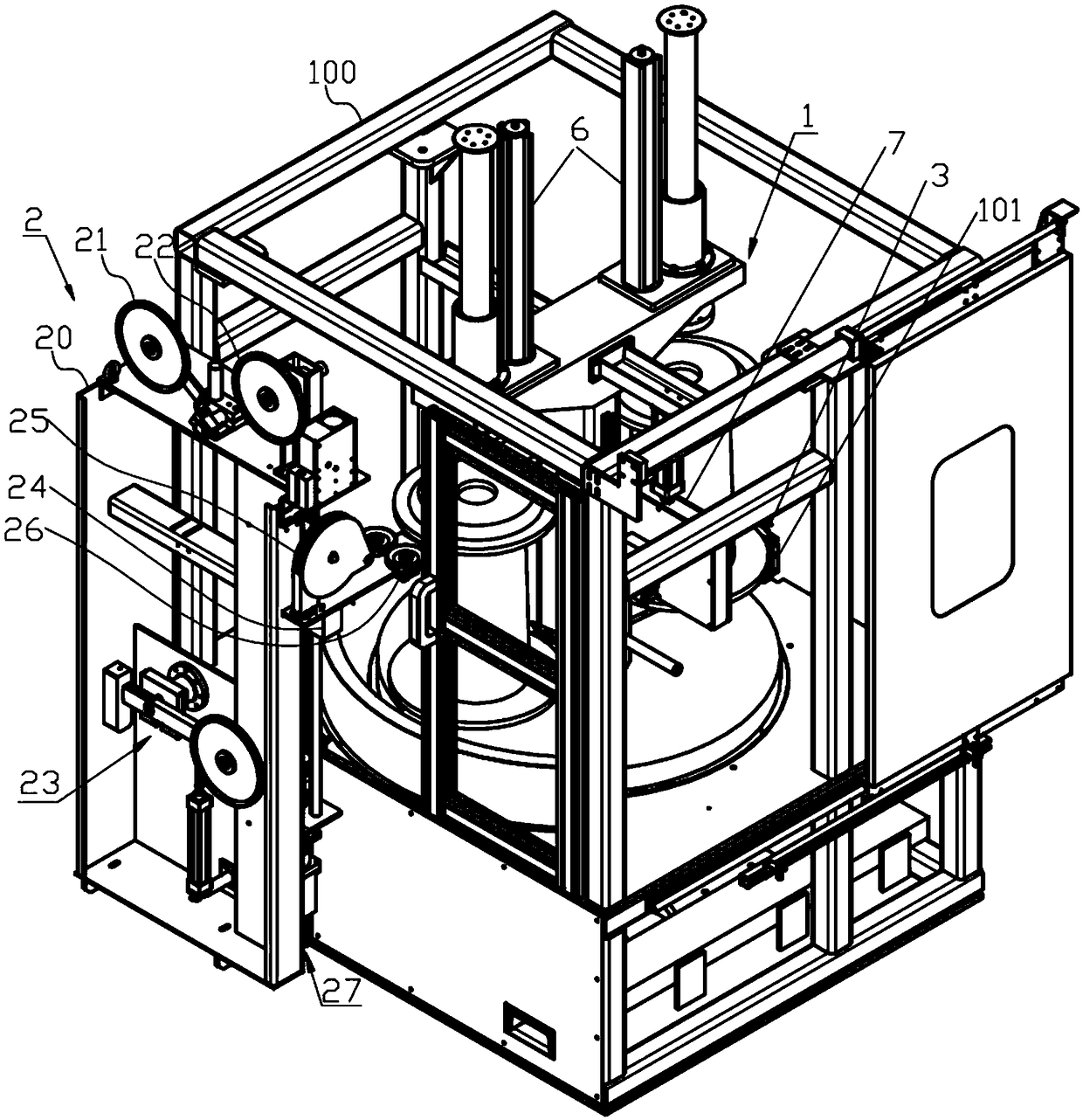
[0037] like figure 1As shown, a wire take-up machine according to an embodiment of the present invention includes a frame 100 , a turntable type wire take-up device 1 , and a wire support 2 disposed on the side of the frame 100 .

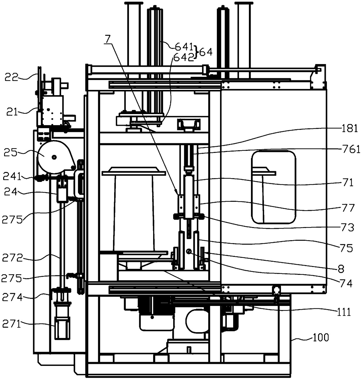
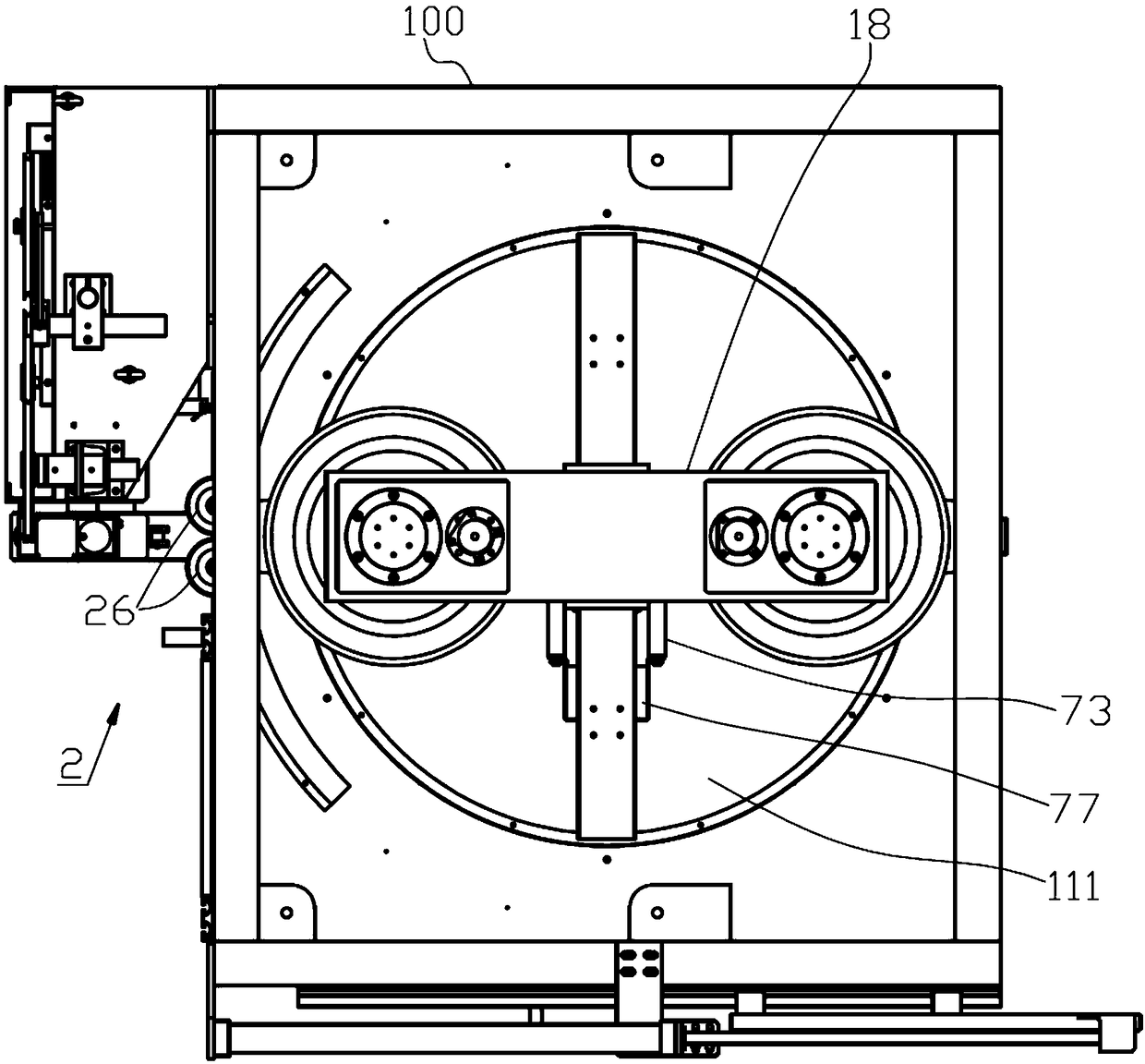
[0038] like figure 2 and 4 As shown, the wire support 2 includes a support 20, a first wire passing wheel 21 and a second wire passing wheel 22 installed on the upper part of the support 20, a tension swing rod mechanism 23 installed at the lower part of the support 20, and integrated on the wire guide block 24. The first wiring wheel 25 and two horizontally arranged second wiring wheels 26, the bracket 20 is provided with a wiring displacement driving mechanism 27 on one side of the bracket 20 close to the turntable type wire take-up device 1, and the wiring displacement driving mechanism 27 connects the wiring The guide block 24 drives the ...


PUM


Abstract

The invention discloses a take-up machine. The take-up machine comprises a rack, a conductive wire support and a rotary-disc take-up device, wherein the rotary-disc take-up device comprises a rotary disc and two groups of take-up shafts symmetrically installed on the rotary disc; a take-up carrying plate is connected to each take-up shaft; the rotary disc is connected with a rotary disc shaft, andthe rotary disc shaft is driven through a rotary disc drive mechanism to drive the rotary disc to rotate; a take-up disc drive mechanism driving each take-up shaft to rotate is connected to the lowerpart of the take-up shaft; a disc pressing mechanism is arranged above the rotary disc; a wire pressing mechanism is arranged between the two groups of take-up carrying plates and in a manner of deflecting from one side of the rotary disc shaft; and enameled wires sequentially round a first wire crossing wheel, a tension swing rod mechanism, a second wire crossing wheel and a first wire arrangement wheel of the conductive wire support, and then passes through the space between two second wire arrangement wheels and are led onto take-up discs on the take-up carrying plates. According to the take-up machine, the take-up discs can be placed in place, a smooth take-up process is achieved, and the enameled wires can be uniformly wound on the take-up discs; and rapid switchover for the positions of the two take-up discs is carried out by virtue of the rotary disc, and automatic wire laying, disc switchover and wire breakage are realized, so that the need of high-speed production is met.

Description

technical field [0001] The invention relates to enameled wire manufacturing equipment, and more particularly to a wire take-up machine. Background technique [0002] The enameled wire is composed of the inner wire and the coating that wraps the wire. After the enameled wire is annealed, painted, baked, cooled, etc., the enameled wire needs to be arranged on the take-up reel through the wire take-up device. In the wire take-up device, the enameled wire cooperates with the high-speed rotating take-up reel through the wire guide wheel, and the take-up reel is fixed in the wire take-up device. The enameled wire led out by the wire guide pulley is wound on the wire take-up reel. [0003] The wire take-up and arrangement device in the prior art has some deficiencies: First, the wire-arranging process of the enameled wire cannot be carried out stably and orderly, resulting in uneven enameled wire wound on the take-up reel. The tension will increase, and the enameled wire will be ...

Claims


Application Information

Patent Timeline
Patent Type & Authority Applications(China)
IPC IPC(8): B65H59/10B65H54/28B65H54/54B65H54/70
CPCB65H54/28B65H54/54B65H54/70B65H59/10
Inventor 蔡麟张伟新惠渊
Owner WUXI JUYI TONGCHUANG TECH CO LTD
Why Eureka
Try Eureka