Long and thin column glass rod clamping device

A clamping device and glass rod technology, which is applied in the field of automatic production of optical lenses, can solve the problems of warping and deformation, not satisfying automatic clamping, etc., achieve the effects of small deformation at high temperature, solve the problem of optical lens falling, and high mechanical strength

Active Publication Date: 2019-02-15
西安天穹智能机器科技有限公司
View PDF6 Cites 1 Cited by
  • Summary
  • Abstract
  • Description
  • Claims
  • Application Information

AI Technical Summary

Problems solved by technology

[0002] In the pre-installation process of optical lens coating, it is required to fix the optical lens in the fixture according to the process requirements. At present, the clamping of the optical lens is completely operated manually, and the used fixture is vacuum coated for a long time in a high temperature environment, which is prone to Warping deformation, does not meet the requirements for automatic card loading
There is no clamping device capable of automatically controlling the optical lens in the prior art

Method used


Image

  • Long and thin column glass rod clamping device
  • Long and thin column glass rod clamping device
  • Long and thin column glass rod clamping device

Examples


Embodiment Construction

[0031] The present invention will be described in detail below in conjunction with the accompanying drawings and embodiments.

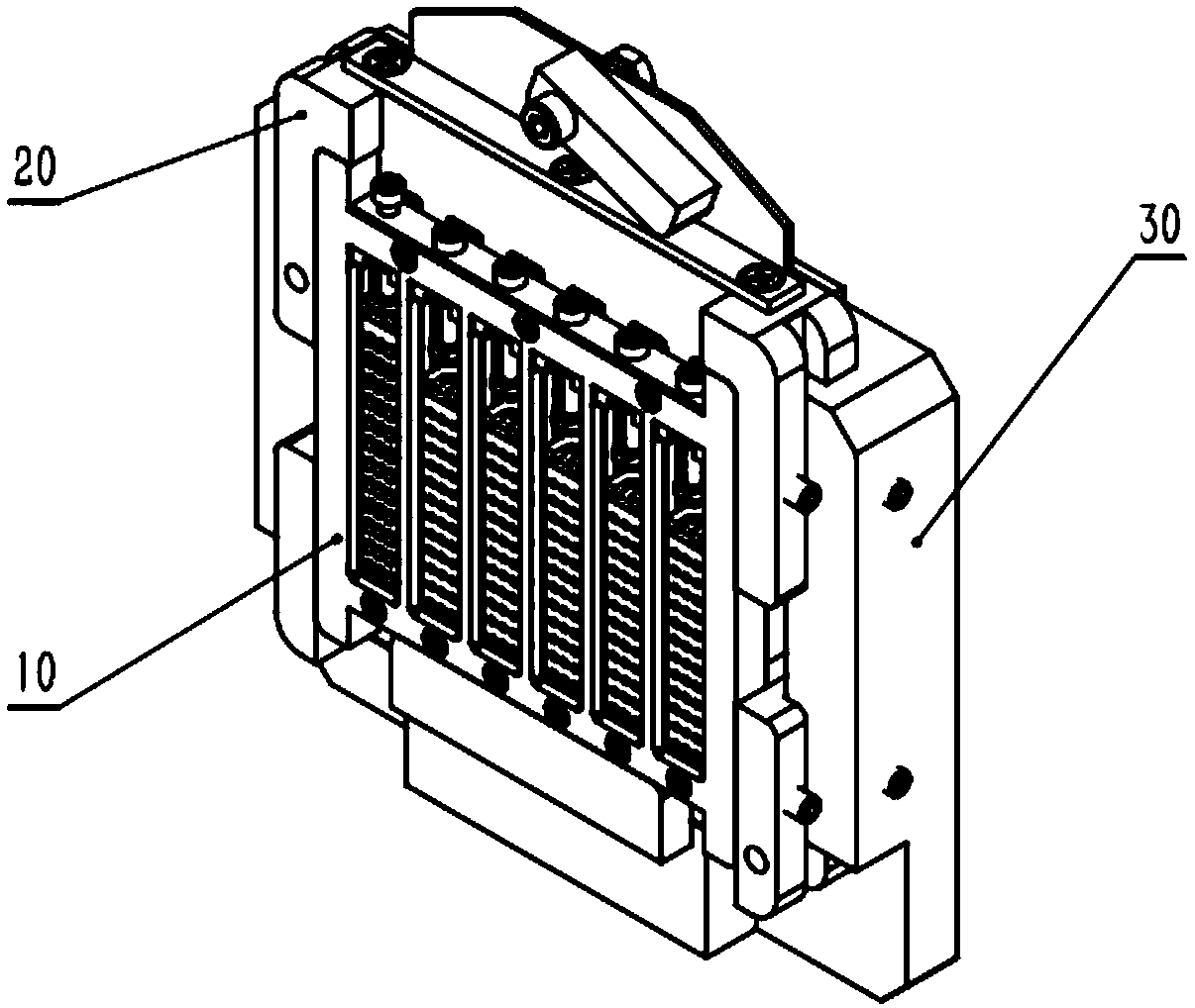
[0032] refer to figure 1 , a clamping device for a slender cylindrical glass rod, comprising a clamp 10 , a clamping fixture 20 and a fixing base 30 . The clamp 10 is installed on the clamping and fixing jig 20 , and the clamping and fixing jig 20 is installed on the fixing seat 30 .

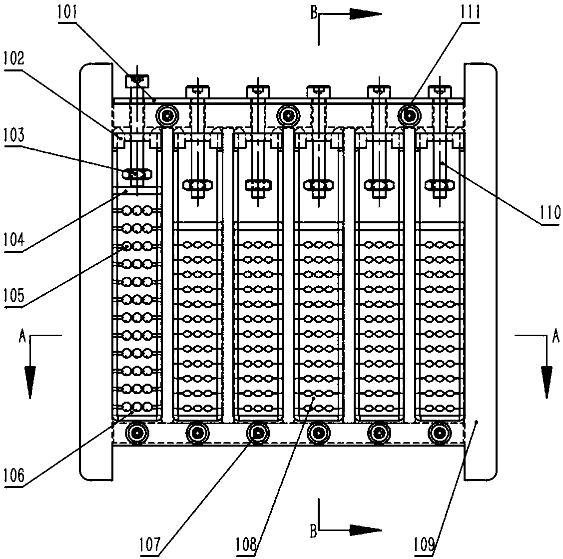
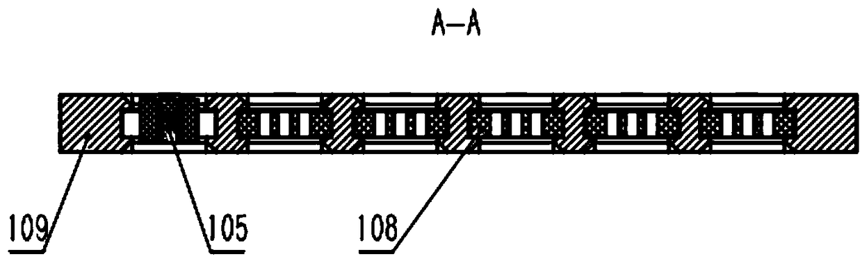
[0033] refer to figure 2 , image 3 , Figure 4 with Figure 5 , the clamp 10 includes an integrated bracket 109, and the integrated bracket 109 is integrally processed with 6 sets of guide grooves by wire cutting, and a single-sided clamping block 106 and a double-sided clamping block 108 are placed in the guide grooves. The block 106 and the double-sided clamping block 108 cooperate to clamp the optical lens 105, and the single-sided clamping block 106 and the double-sided clamping block 108 can slide freely along the guide groove; the top single-sided clamping ...


PUM


Abstract

The invention discloses a long and thin column glass rod clamping device which comprises a clamp, wherein the clamp is mounted on a clamping fixing jig; the clamping fixing jig is mounted on a fixingbase; the clamp comprises an integral bracket; a plurality groups of guide grooves are formed in the integral bracket; single-side clamping blocks and double-side clamping blocks are placed inside theguide grooves; the single-side clamping blocks and the double-side clamping blocks cooperate to clamp optical lenses; tetrafluorohydrazine pads on the single-side clamping blocks are connected with bottom ends of fixing screws; the fixing screws penetrate through the integral bracket; the integral bracket is connected with the clamping fixing jig; the clamping fixing jig comprises a fixing platefor fixing the integral bracket; a plurality groups of elastic pieces are arranged corresponding to the clamp on the fixing plate; the elastic pieces are used for constantly pressing the single-side clamping blocks and the double-side clamping blocks through compression springs; bulges on the back sides of the elastic pieces are clamped in long stripy holes of elastic plates; the elastic plates are hinged with rotating shifting forks; the rotating shifting forks are used for enabling the plurality groups of the elastic pieces to be lifted up simultaneously and be dissociated from top-layer single-side clamping blocks through cooperation of a pressing plate and the elastic plate. By adopting the device, automatic assembling and clamping can be achieved.

Description

technical field [0001] The invention belongs to the technical field of automatic production of optical lenses, and in particular relates to a clamping device for elongated cylindrical glass rods. Background technique [0002] In the pre-installation process of optical lens coating, it is required to fix the optical lens in the fixture according to the process requirements. At present, the clamping of the optical lens is completely operated manually, and the used fixture is vacuum coated for a long time in a high temperature environment, which is prone to Warping deformation does not meet the requirements for automatic card loading. There is no clamping device capable of automatically controlling the optical lens in the prior art. Contents of the invention [0003] In order to overcome the above-mentioned shortcomings of the prior art, the object of the present invention is to provide a clamping device for elongated cylindrical glass rods, which can realize automatic clamp...

Claims


Application Information

Patent Timeline
Patent Type & Authority Applications(China)
IPC IPC(8): C03C17/00
CPCC03C17/001Y02P40/57
Inventor 王新朝白稳继翟银燕田源李卫中
Owner 西安天穹智能机器科技有限公司
Why Eureka
Try Eureka