Method for constructing underground continuous wall by using cutter-suction head

A technology of underground diaphragm wall and cutter suction, applied in sheet pile wall, foundation structure engineering, construction and other directions, can solve problems such as construction difficulties, achieve the effect of fast excavation, increase construction speed, and ensure safety

Inactive Publication Date: 2019-02-15
GEOTECHN TECH
View PDF8 Cites 1 Cited by
  • Summary
  • Abstract
  • Description
  • Claims
  • Application Information

AI Technical Summary

Problems solved by technology

[0005] The purpose of the present invention is to overcome the shortcomings of the equipment used in the construction of the underground diaphragm wall in the prior art, which have high req

Method used


Image

  • Method for constructing underground continuous wall by using cutter-suction head
  • Method for constructing underground continuous wall by using cutter-suction head

Examples


Embodiment Construction

[0025] The present invention will be further described below in conjunction with the accompanying drawings and specific embodiments.

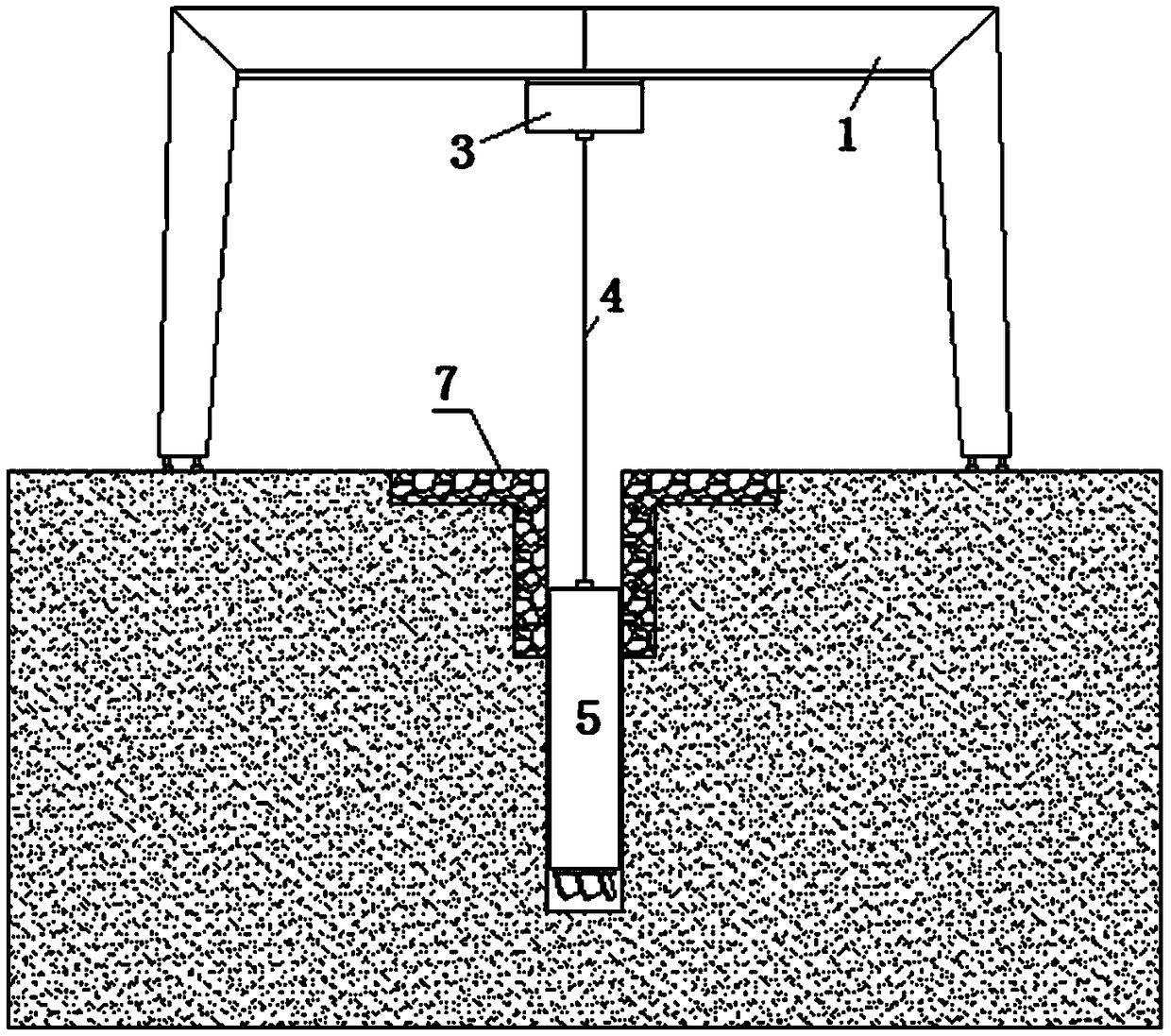
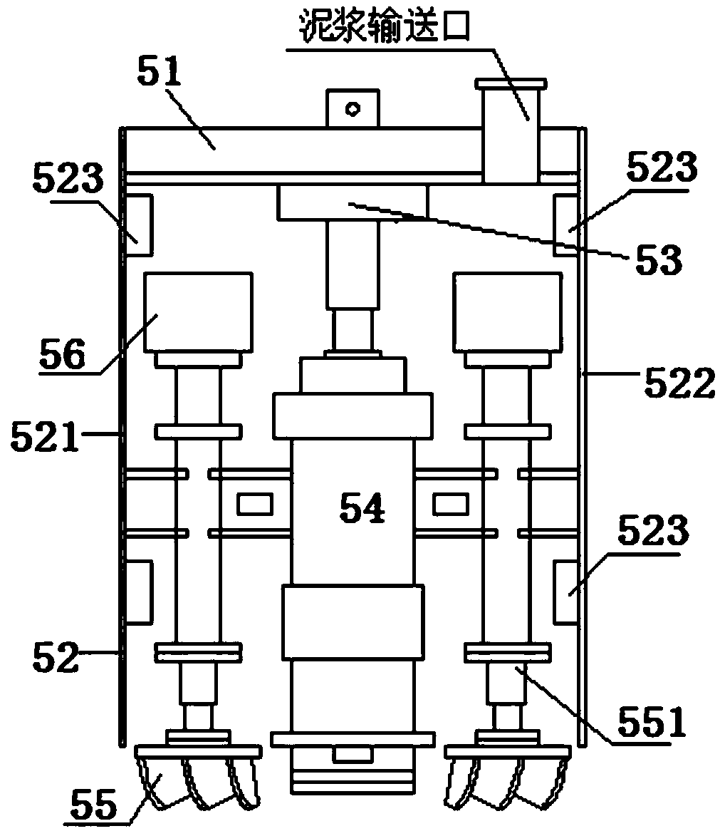
[0026] Such as figure 1 , figure 2 The illustrated embodiment is a method for constructing an underground diaphragm wall using a twisted suction head, including five cranes 1, a mud-water separator, a track 3 arranged on the lower surface of each crane, and a driving power device arranged on the track to pass through The wire rope 4 is connected with the hinge suction head 5; the hinge suction head includes a beam 51, a rectangular tube 52 arranged on the beam at the upper end and a lower end opening, a hydraulic device 53 connected to the middle part of the lower surface of the beam, and a slurry connected to the connecting rod of the hydraulic device. The pump 54 is arranged on two reamers 55 on both sides of the mud pump; the mud pump is fixedly connected to the connecting shafts 551 of the two reamers respectively, and the two connecting ...


PUM


Abstract

The invention discloses a method for constructing an underground continuous wall by using a cutter-suction head. The method for constructing the underground continuous wall by using the cutter-suctionhead is characterized in that a plurality of travelling cranes, a mud-water separator and tracks are included, wherein the tracks are arranged on the lower surfaces of the travelling cranes, and travelling crane power devices arranged on the tracks are connected with the cutter-suction head through wire ropes; the cutter-suction head comprises a transverse beam, a rectangular cylinder arranged atupper and lower end openings of the transverse beam, a hydraulic device connected to the middle part of the lower surface of the transverse beam, a mud pump connected with a connecting rod of the hydraulic device and two reamers arranged on both sides of the mud pump; and the mud pump is fixedly connected with connecting shafts of the two reamers correspondingly, and the two connecting shafts areconnected with two reamer motors correspondingly. The method for constructing the underground continuous wall by using the cutter-suction head has the characteristic that the underground continuous wall construction can be carried out on a narrow site.

Description

technical field [0001] The invention relates to the technical field of diaphragm wall construction, in particular to a method for constructing an underground diaphragm wall by using a twisting suction head with high construction efficiency. Background technique [0002] The underground diaphragm wall is a long and narrow deep groove excavated on the ground along the peripheral axis of the deep excavation project under the condition of the mud retaining wall. After the groove is cleaned, the steel cage is hung in the groove , and then use the conduit method to pour underwater concrete to form a unit tank section, and then proceed section by section to form a continuous reinforced concrete wall underground as a water interception, anti-seepage, load-bearing, and water-retaining structure. [0003] Utilize hydraulic grab bucket (grooving machine) during present underground diaphragm wall construction to carry out digging into groove, utilize hydraulic groove milling machine to ...

Claims


Application Information

Patent Timeline
IPC IPC(8): E02D5/18
CPCE02D5/187
Inventor 殷树芳潘金龙楼耀威
Owner GEOTECHN TECH
Why Eureka
Try Eureka