Air conditioner internal unit and air conditioner

An air conditioner internal unit and heat exchanger technology, which is applied in air conditioning systems, space heating and ventilation, space heating and ventilation details, etc. problems, to achieve the effect of increasing the air volume, improving the heat exchange efficiency, and avoiding the problem of return air

Pending Publication Date: 2019-02-15
GREE ELECTRIC APPLIANCES INC
View PDF0 Cites 1 Cited by
  • Summary
  • Abstract
  • Description
  • Claims
  • Application Information

AI Technical Summary

Problems solved by technology

[0002] Traditional wall-mounted air conditioners have only one air inlet, air outlet, and fan. Whether it is heating or cooling, the air comes out of one air outlet, and the comfort cannot achieve the best effect.
Since there is only one air inlet and the air inlet area is limited, it is impossible to further increase the air intake and improve the heat exchange efficiency, and the heat exchange efficiency between the air blown by the air conditioner and the indoor air is seriously affected by the wind speed and the air output volume, and the wind speed and air volume cannot be further improved. Improvement, so the heat transfer efficiency cannot be improved, thereby further improving the comfort
[0003] In the existing air conditioner, a kind of air conditioner with upper and lower air outlets is proposed. The air outlet of the air conditioner is located on the upper and lower sides, and the air inlet is located on the front panel. The distance between the air outlets is relatively short, so it is easy to cause the air from the air conditioner to enter the air conditioner directly from the air inlet on the front panel, causing the air return problem of the air conditioner, making the air volume unable to increase, and affecting the heating / cooling capacity of the air conditioner

Method used


Image

  • Air conditioner internal unit and air conditioner
  • Air conditioner internal unit and air conditioner
  • Air conditioner internal unit and air conditioner

Examples


Embodiment Construction

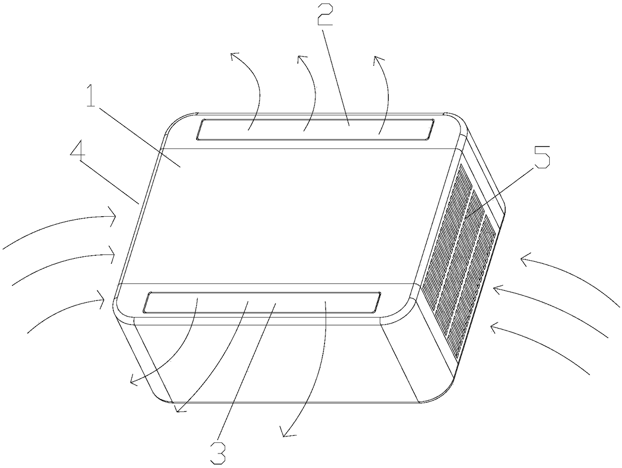
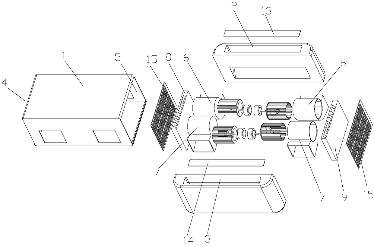
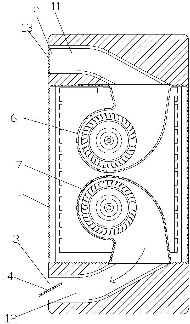
[0029] see in conjunction Figure 1 to Figure 5 As shown, according to the embodiment of the present invention, the air conditioner indoor unit includes a housing 1, the housing 1 is provided with an upper air outlet 2 and a lower air outlet 3, and the housing 1 is also provided with a left air inlet 4 and / or a right air inlet The air outlet 5, the upper air outlet 2 is located on the top plate and / or the front panel of the housing 1, the lower air outlet 3 is located on the bottom plate and / or the front panel of the housing 1, and the left air inlet 4 is located on the left side panel of the housing 1 , the right air inlet 5 is located on the right side plate of the housing 1.

[0030] The air outlet of the indoor unit of the air conditioner is located on the upper and lower sides, and the air inlet is located on the left and / or right side, so the distance between the air inlet and outlet can be increased to prevent the air from the inner unit of the air conditioner from dire...


PUM


Abstract

The invention provides an air conditioner internal unit and an air conditioner. The air conditioner internal unit comprises a shell (1) which is provided with an upper air outlet (2) and a lower air outlet (3), and further provided with a left air inlet (4) and/or a right air inlet (5); the upper air outlet (2) is located in a top plate and/or a front panel of the shell (1); the lower air outlet (3) is located in a bottom plate and/or a front panel of the shell (1); and the left air inlet (4) is located in a left side plate of the shell (1), and the right air inlet (5) is located in a right side plate of the shell (1). The air conditioner internal unit can solve the problem that air returning happens to the air conditioner internal unit, and the air outflow amount is increased.

Description

technical field [0001] The invention belongs to the technical field of air conditioning, and in particular relates to an air conditioner inner unit and an air conditioner. Background technique [0002] Traditional wall-mounted air conditioners have only one air inlet, outlet, and fan. Whether it is heating or cooling, the air comes out of one air outlet, and the comfort cannot achieve the best effect. Since there is only one air inlet and the air inlet area is limited, it is impossible to further increase the air intake and improve the heat exchange efficiency, and the heat exchange efficiency between the air blown by the air conditioner and the indoor air is seriously affected by the wind speed and the air output volume, and the wind speed and air volume cannot be further improved. Therefore, the heat exchange efficiency cannot be improved, thereby further improving the comfort. [0003] In the existing air conditioner, a kind of air conditioner with upper and lower air ou...

Claims


Application Information

Patent Timeline
Patent Type & Authority Applications(China)
IPC IPC(8): F24F1/0003F24F1/0014F24F1/0022F24F1/0033F24F1/0063F24F13/08F24F13/14F24F13/30
CPCF24F1/0003F24F1/0014F24F1/0022F24F1/0033F24F1/0059F24F13/08F24F13/1413F24F13/30
Inventor 宁强延李振华李强刘慧黄煜鹏杨永祥黄林李开华
Owner GREE ELECTRIC APPLIANCES INC
Why Eureka
Try Eureka