Furnace wall cleaning device for smelting furnace

A technology for cleaning devices and smelting furnaces, used in descaling devices, furnaces, furnace components, etc., can solve the problems of incomplete cleaning inside the furnace wall, inability to adjust the height, and dead corners of the furnace wall.

Active Publication Date: 2019-02-15
广东华劲金属型材有限公司
View PDF8 Cites 0 Cited by
  • Summary
  • Abstract
  • Description
  • Claims
  • Application Information

AI Technical Summary

Problems solved by technology

[0012] The present invention provides a cleaning device for the furnace wall of a smelting furnace through improvement. By setting a lifting mechanism and turning the runner, the screw rod is driven by it to rotate, so that the slide rod and the screw rod are threadedly connected to slide left and right on the inner side of the top plate, driving the first bracket. Adjust up and down with the second bracket to raise the top plate, thereby driving the equipment components on the upper end of the support plate to adjust the height, which solves the problem that the height cannot be adjusted and cleaned, and the dead angle inside the furnace wall is not easy to clean. By setting For the winding device, when the spray gun is not used for cleaning work, grasp the handle at the bottom side of the hand wheel and turn the hand wheel, so that it drives the right rotating plate and the left rotating plate to rotate, and at the same time drives the drum to rotate. After turning, the water delivery pipe is wound into the arc-shaped groove outside the drum to complete the storage of the water delivery pipe, which solves the problem that the length of the water delivery pipe is too long, it is not convenient for collection and management, and it takes up a lot of space. By setting up a descaling device, After the motor works, it drives the first transmission shaft t...

Method used


Image

  • Furnace wall cleaning device for smelting furnace
  • Furnace wall cleaning device for smelting furnace
  • Furnace wall cleaning device for smelting furnace

Examples


Embodiment Construction

[0062] The following will be combined with Figure 1-9 The present invention is described in detail, and the technical solutions in the embodiments of the present invention are clearly and completely described. Apparently, the described embodiments are only some of the embodiments of the present invention, not all of them. Based on the embodiments of the present invention, all other embodiments obtained by persons of ordinary skill in the art without making creative efforts belong to the protection scope of the present invention.

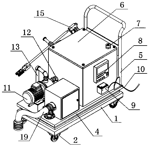
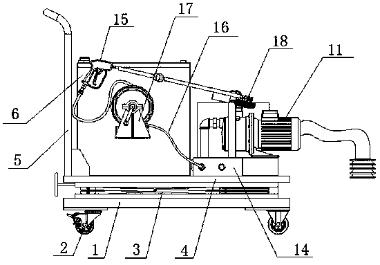
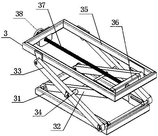
[0063] The present invention provides a smelting furnace wall cleaning device through improvement, including a base 1, a walking wheel 2, a support plate 4, a push rod 5, a water storage tank 6, a water filling port 7, a control panel 8, a storage battery 9, and a power cord 10. Water pump 11, first connecting pipe 12, second connecting pipe 13, adapter 14, spray gun 15, water pipe 16, lifting mechanism 3, winding device 17, descaling device 18 and ...


PUM

PropertyMeasurementUnit
Lengthaaaaaaaaaa

Abstract

The invention discloses a furnace wall cleaning device for a smelting furnace. The furnace wall cleaning device comprises a base, walking wheels, a supporting plate, a pushing rod, a water storage tank, a water adding opening, a control panel, a storage battery, a power line, a water pump, a first connecting pipe, a second connecting pipe, an adapter, a spraying gun, a water conveying pipe, a lifting mechanism, a winding device, a descaling device and a dust suction device. Through the arrangement of the descaling device, a first transmission shaft is driven to rotate after a motor works, andthe first transmission shaft rotates to drive a first rotating roller to rotate; meanwhile, a main gear outside the first transmission shaft is driven to rotate, and through the meshing with the maingear, an auxiliary gear is enabled to rotate; the auxiliary gear rotates to drive a second transmission shaft to rotate so that the second rotating roller can be driven to rotate, and the first rotating roller and the second rotating roller rotate and are in contact with the furnace wall to perform descaling work; and the problem that the interior of the furnace wall is not thoroughly cleaned dueto the fact that residues are attached to the interior of the furnace wall is solved.

Description

technical field [0001] The invention relates to the related field of smelting furnace cleaning, in particular to a device for cleaning the furnace wall of a smelting furnace. Background technique [0002] The smelting furnace refers to the equipment that melts metal ingots and some scrap metals and adds the necessary alloy components, and smelts them into the required alloys through operations such as slag removal and refining. , Metal residues will adhere to the inner surface of the furnace wall, which needs to be cleaned to ensure the quality of subsequent metal processing. [0003] After searching, it is found that the invention of patent No. CN201220314441.5 discloses a slag removal device for a smelting furnace, which includes a frame and a rake bar. The loose sleeve is on the rotating shaft, and elastic plates are arranged on both sides of the rake bar, and the elastic plates are pressed on both sides of the rake bar. [0004] After searching, it is found that the in...

Claims


Application Information

Patent Timeline
IPC IPC(8): F27D25/00
CPCF27D25/008
Inventor 周建炎凌大伟
Owner 广东华劲金属型材有限公司
Why Eureka
Try Eureka