
Through hole thread detection equipment

A detection equipment and thread technology, applied in the field of through-hole thread detection equipment, can solve the problems of low detection efficiency and high labor intensity of workers, and achieve the effect of improving clamping efficiency

Pending Publication Date: 2019-02-15
张枫
View PDF0 Cites 1 Cited by
  • Summary
  • Abstract
  • Description
  • Claims
  • Application Information

AI Technical Summary

Problems solved by technology

[0003] At present, the detection of thread is mainly divided into the detection of bottom hole depth and thread size accuracy. The depth of bottom hole is detected by depth gauge, and the thread size accuracy is detected by go-no-go gauge. However, the above inspections are all done manually. Parts with holes, resulting in greater labor intensity for workers and lower detection efficiency

Method used


Image

  • Through hole thread detection equipment
  • Through hole thread detection equipment

Examples


Embodiment Construction

[0017] The specific implementation manners of the present invention will be further described in detail below in conjunction with the accompanying drawings and embodiments. The following examples are used to illustrate the present invention, but are not intended to limit the scope of the present invention.

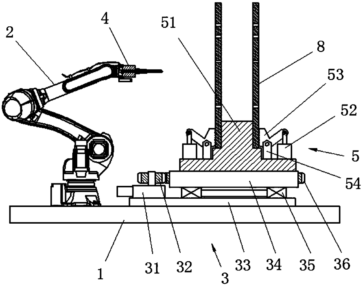
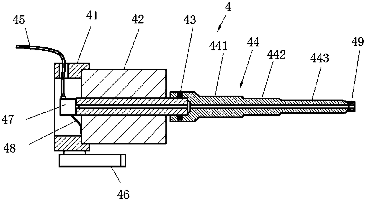
[0018] Such as figure 1 with 2 As shown, a preferred embodiment of the present invention, this kind of through-hole thread detection equipment includes a base 1, a manipulator 2, a rotating assembly 3, a detection assembly 4 and a clamping and positioning assembly 5; the base 1 is horizontally arranged, and the manipulator 2 is set on the upper end of the base 1, the detection component 4 is set on the movable end of the manipulator 2, the rotating component 3 is set on the upper end of the base 1, and the clamping and positioning component 5 is set on the upper end of the rotating component 3, so that the clamping and positioning component can clamp and position Parts, ...


PUM


Abstract

The invention relates to the technical field of industrial detection equipment, in particular to a piece of through hole thread detection equipment. Thread detection is accomplished by manual operation. For the detection of a large number of parts with a large number of threaded holes, the labor intensity of workers is great, and the detection efficiency is low. According to the equipment, a baseis arranged horizontally, a manipulator is arranged on the upper end of the base, a detection component is arranged at the movable end of the manipulator, a rotating component is arranged on the upperend of the base, and a clamping and positioning component is arranged on the upper end of the rotating component. Thus, the clamping and positioning component can clamp and position a part, the rotating component can rotate and position the clamping and positioning component, and the detection component can detect the depth and thread size of a detected bottom hole under the positioning and driving of the manipulator. The detection efficiency is improved. The through hole thread detection equipment is mainly used for through hole thread detection.

Description

technical field [0001] The invention relates to the technical field of industrial testing equipment, in particular to a through-hole thread testing equipment. Background technique [0002] In machining, the thread is cut on a cylindrical shaft or the surface of the inner hole with a tool or a grinding wheel. At this time, the workpiece rotates once, and the tool moves a certain distance along the axis of the workpiece. The tool is on the workpiece. The cut marks are the threads. The threads formed on the outer surface are called external threads. The threads formed on the surface of the inner hole are called internal threads. The basis of the thread is the helix on the surface of the circular shaft. Usually, if the cross-section of the thread is triangular, it is called triangular thread; if the cross-section is trapezoidal, it is called trapezoidal thread; if the cross-section is zigzag, it is called zigzag thread; if the cross-section is square, it is called square thre...

Claims


Application Information

Patent Timeline
IPC IPC(8): G01B5/00
CPCG01B5/0002
Inventor 张枫
Owner 张枫
Learn More