Detecting equipment for fan blades of wind turbine

A technology for wind power generators and testing equipment, which is applied in the direction of measuring devices, optical testing of flaws/defects, and analysis of solids using sound waves/ultrasonic waves/infrasonic waves. Efficiency and other issues, to achieve the effect of easy repair, reduce strength, and realize automatic processing

Pending Publication Date: 2019-02-15
杭州戬威科技有限公司
View PDF1 Cites 2 Cited by
  • Summary
  • Abstract
  • Description
  • Claims
  • Application Information

AI Technical Summary

Problems solved by technology

However, in the process of producing wind turbines, it is necessary to conduct a comprehensive and systematic inspection of the fan blades before leaving the factory to ensure that the installed fan blades will not be damaged, but in the process of inspecting the fan blades , especially using mechanical equipment for detection, the equipment is usually located on the upper end surface of the fan blade, although the detection efficiency is high, but because the weight of the mechanical equipment is usually heavy, when the fan blade needs to be turned over or removed, It is necessary to manually remove the entire device, and then manually put the device on. This process consumes a lot of time and manpower, which will greatly affect the efficiency of fan blade detection.

Method used


Image

  • Detecting equipment for fan blades of wind turbine
  • Detecting equipment for fan blades of wind turbine
  • Detecting equipment for fan blades of wind turbine

Examples


Embodiment 1

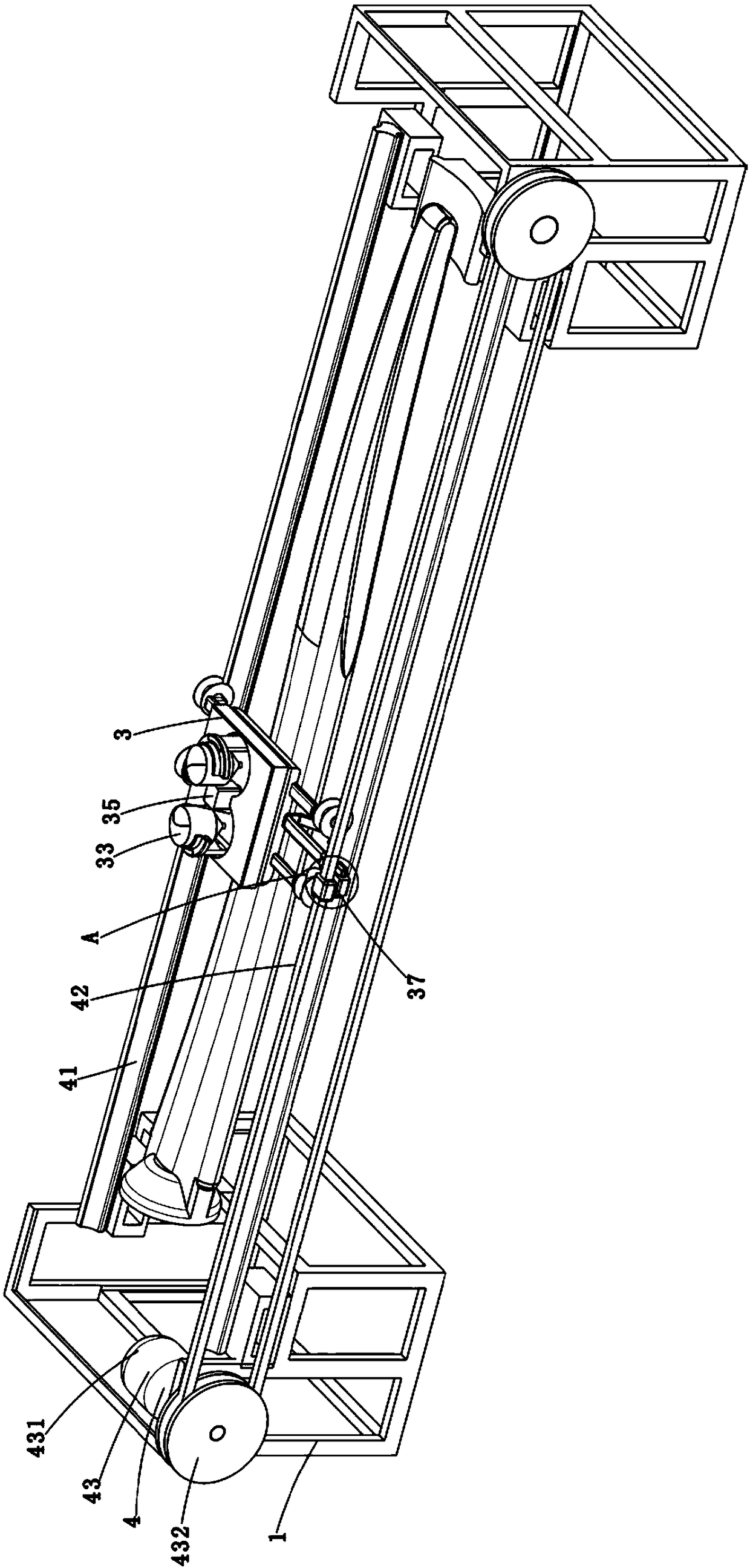
[0039] Such as Figure 1-11 As shown, a detection device for wind turbine blades includes a frame 1, a detection device 2, a marking device 3 and a driving device 4, wherein the frame 1 is a metal frame, and the frame 1 is two , the fan blades are mounted on two racks 1; the detection device 2 can scan and image the surface of the fan blades, and then transmit the collected images to the computer in real time through radio technology, and manually Cracks and damages on the fan blades are directly judged in front of the computer. The detection device 2 includes a plurality of cameras 21 and a lower road plate 22. It is a prior art, so it will not be described in detail here; When the device 2 finds damage and cracks, draw two marking lines on the surface of the fan blade, and the damage and cracks are between the two marking lines; the driving device 4 can be used to pull the marking device 3 to move forward and backward, and The driving device 4 supplies power to the detectio...

Embodiment 2

[0048] Such as Figure 12-14 As shown, this implementation discloses a pull-off device 5 for moving the marking device away from the driving device, and the pull-off device 5 is arranged on the frame 1; specifically: the pull-off device 5 includes a mechanical claw part 51, a lifting part 52 and a rotating part 53. The mechanical claw part 51 includes an n-shaped mechanical arm 511, a grasping part 512 and an anti-off part 513. The mechanical arm 511 is a metal arm. The gripper 512 is connected to one end of the mechanical arm 511 by screws, the gripper 512 is a metal frame with four n-shaped mechanical claws 516, and each mechanical claw 516 can be set on the frame body On the four legs of 31, there is a pin hole on the mechanical claw 512, and the anti-off piece 513 passes through the pin hole. Specifically, the anti-off piece 513 is a T-shaped metal strip. The end of the anti-off piece 513 has a pin hole, and a T-shaped metal pin can be inserted on the end of the anti-off ...


PUM


Abstract

The invention discloses detecting equipment for fan blades of a wind turbine. The detecting equipment comprises a frame for fixing a fan blade, a detecting device for scanning an end face of the fan blade, a marking device for drawing at least two marking lines on the fan blade when a crack or breakage on the fan blade is detected by the detecting device, and a towing device for moving the markingdevice away from a driving device, wherein the towing device is disposed on the frame. According to the detecting equipment, the marking device and the detecting device can be simultaneously lifted by the towing device in the process of detecting the fan blade by the detecting equipment, so that the marking device can be separated from the driving device, and the fan blade can be conveniently overturned or directly removed, thereby reducing the intensity of manual operation, achieving automatic processing, and effectively improving the efficiency of the entire machining process.

Description

technical field [0001] The invention belongs to the technical field of wind power generation, and in particular relates to a detection device for fan blades of a wind power generator. Background technique [0002] Wind power generation refers to converting the kinetic energy of the wind into mechanical kinetic energy, and then converting the mechanical energy into electrical kinetic energy. It uses wind power to drive the blades of the windmill to rotate, and then increases the speed of rotation through the speed increaser to promote the generator to generate electricity. The wind wheel (Fan blade) is an important part that converts the kinetic energy of the wind into mechanical energy. It consists of two (or more) propeller-shaped impellers. When the wind blows to the blade, the aerodynamic force is generated on the blade to drive the wind wheel to rotate. . The material of the blade requires high strength and light weight. At present, it is mostly made of glass fiber rein...

Claims


Application Information

Patent Timeline
Patent Type & Authority Applications(China)
IPC IPC(8): G01N21/88G01N29/04
CPCG01N21/88G01N29/04G01N29/048
Inventor 方文平
Owner 杭州戬威科技有限公司
Why Eureka
Try Eureka