Distance fuzzy suppression method, device and equipment based on nonlinear orthogonal waveform
An orthogonal waveform and range ambiguity technology, applied in the field of synthetic aperture radar imaging, can solve problems such as range ambiguity, azimuth ambiguity, and high PRF
- Summary
- Abstract
- Description
- Claims
- Application Information
AI Technical Summary
Problems solved by technology
Method used
Image
Examples
Embodiment 1
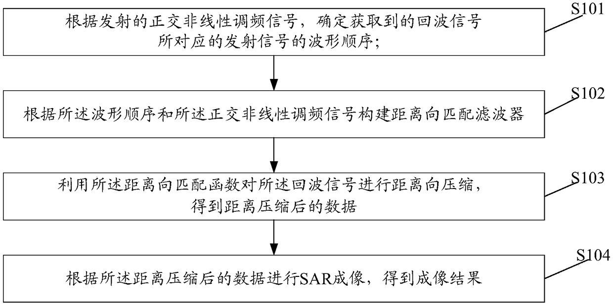
[0038] An embodiment of the present invention provides a range ambiguity suppression method based on a nonlinear orthogonal waveform, figure 1 It is a schematic diagram of the implementation flow of the distance ambiguity suppression method based on the nonlinear orthogonal waveform in the embodiment of the present invention, as shown in figure 1 As shown, the method includes the following steps:
[0039] Step S101, according to the transmitted quadrature non-linear frequency modulation signal, determine the waveform sequence of the transmitted signal corresponding to the acquired echo signal.
[0040] Here, the step S101 may be implemented by a range ambiguity suppression device based on a nonlinear orthogonal waveform, wherein the range ambiguity suppression device based on a nonlinear orthogonal waveform may also be called a SAR imaging device. Further, the SAR imaging device may be an intelligent terminal with computing capability, such as a desktop computer.
[0041] In...
Embodiment 2
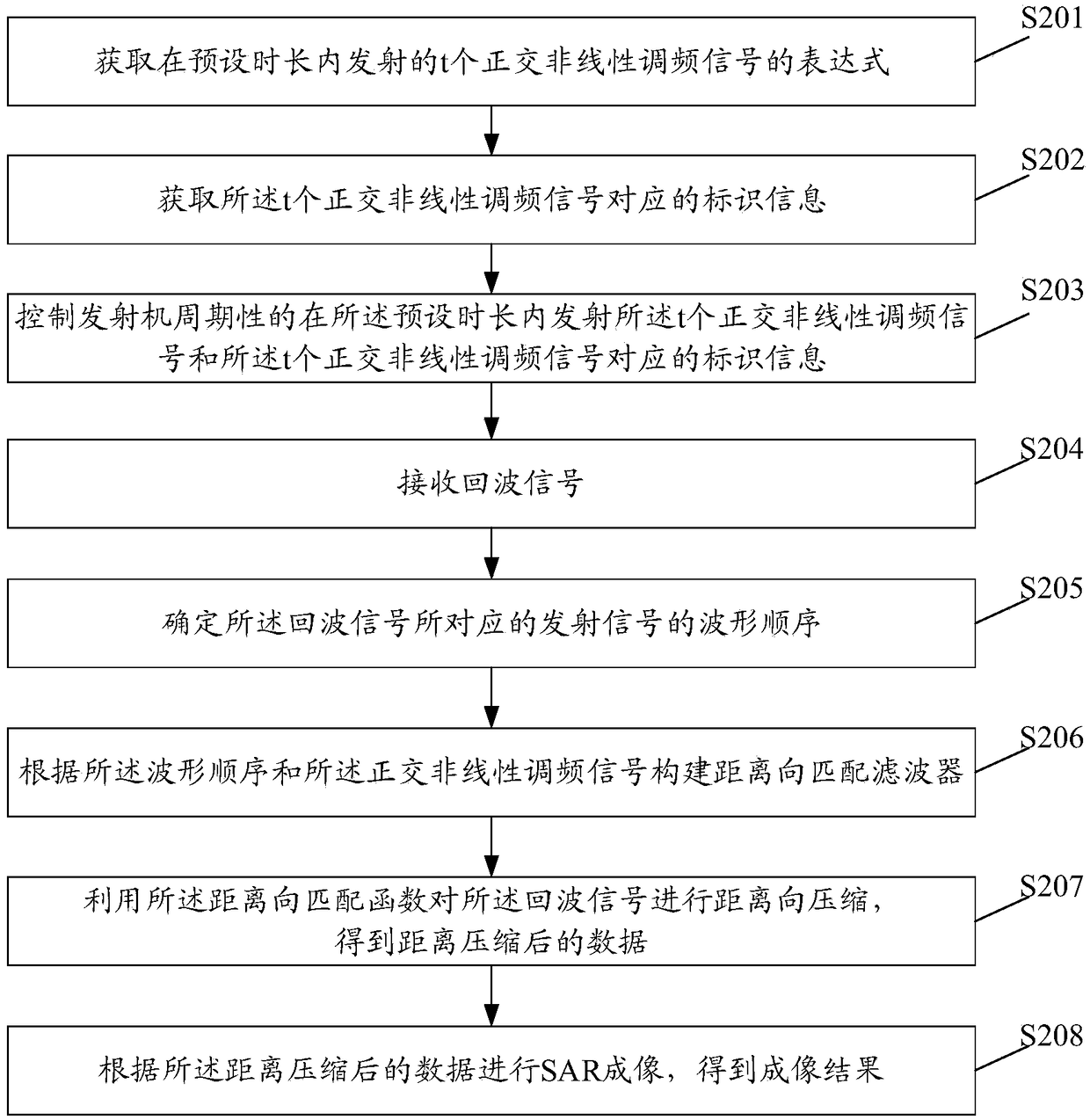
[0056] Based on the foregoing embodiments, embodiments of the present invention provide a range ambiguity suppression method based on a nonlinear orthogonal waveform, which is applied to a range ambiguity suppression device based on a nonlinear orthogonal waveform, that is, a SAR imaging device, figure 2 It is a schematic diagram of the implementation flow of the distance ambiguity suppression method based on the nonlinear orthogonal waveform in the embodiment of the present invention, as shown in figure 2 As shown, the method includes the following steps:
[0057] In step S201, the SAR imaging device acquires t orthogonal non-linear frequency modulation signals transmitted within a preset time period.
[0058] Here, the preset duration is t times the pulse repetition interval, and t is a natural number greater than 1. The quadrature non-linear frequency modulation signal may be artificially set in advance.
[0059] In this embodiment, obtaining t orthogonal non-linear fre...
Embodiment 3
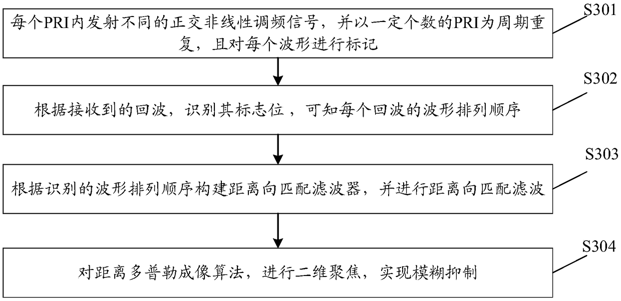
[0088] Based on the foregoing embodiments, embodiments of the present invention further provide a range ambiguity suppression method based on nonlinear orthogonal waveforms, which can suppress range ambiguity by using orthogonal nonlinear frequency modulation signals during SAR imaging. image 3 It is a schematic diagram of the implementation process of SAR imaging in the embodiment of the present invention, such as image 3 As shown, the method includes the following steps:
[0089] Step S301 , when the transmitter transmits a signal, transmit different orthogonal non-linear frequency modulation signals in different PRIs, repeat with a certain number of PRIs as a cycle, and mark each waveform.
[0090] here, as Figure 4 As shown, taking two signals as an example, the signal s is transmitted in the first PRI 1 (t), transmit signal s in the second PRI 2 (t), transmit signal s in the third PRI 1 (t), transmit signal s in the fourth PRI 2 (t), so that the signal is transmit...
PUM
 Abstract
Description
Claims
Application Information
 - R&D
- Intellectual Property
- Life Sciences
- Materials
- Tech Scout
- Unparalleled Data Quality
- Higher Quality Content
- 60% Fewer Hallucinations
Browse by: Latest US Patents, China's latest patents, Technical Efficacy Thesaurus, Application Domain, Technology Topic, Popular Technical Reports.
© 2025 PatSnap. All rights reserved.Legal|Privacy policy|Modern Slavery Act Transparency Statement|Sitemap|About US| Contact US: help@patsnap.com


