
A Rotor Position Estimation Method for Permanent Magnet Direct Drive Wind Turbines

A wind turbine and rotor position technology, which is applied in the direction of generator circuit layout control, generator control, motor generator control, etc., can solve the problem of low rotor position estimation accuracy, and achieve faster system response speed and high rotor position estimation. accuracy, the effect of accurate rotor position estimation

Active Publication Date: 2022-05-13
SHENYANG POLYTECHNIC UNIV
View PDF6 Cites 0 Cited by
  • Summary
  • Abstract
  • Description
  • Claims
  • Application Information

AI Technical Summary

Problems solved by technology

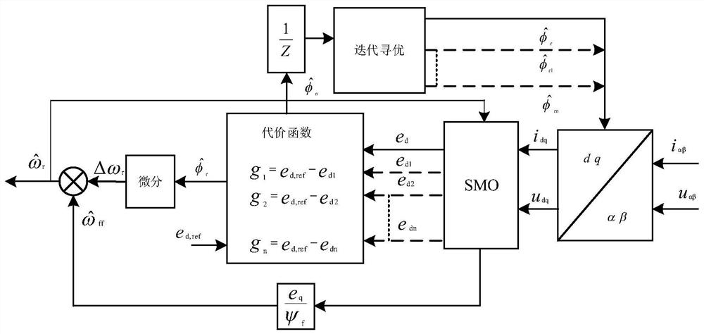
[0004] The invention provides a method for estimating the rotor position of a permanent magnet direct drive wind power generator. Through the flux linkage tracking of the rotor, an iterative optimization algorithm is set to accurately find the rotor position information of the permanent magnet wind power generator to solve the problem of the permanent magnet wind power generator. The Problem of Low Accuracy of Position Sensorless Rotor Position Estimation

Method used


Image

  • A Rotor Position Estimation Method for Permanent Magnet Direct Drive Wind Turbines
  • A Rotor Position Estimation Method for Permanent Magnet Direct Drive Wind Turbines
  • A Rotor Position Estimation Method for Permanent Magnet Direct Drive Wind Turbines

Examples


Embodiment Construction

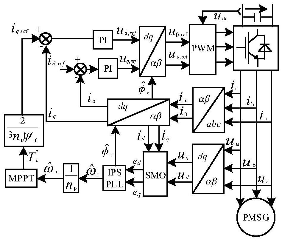
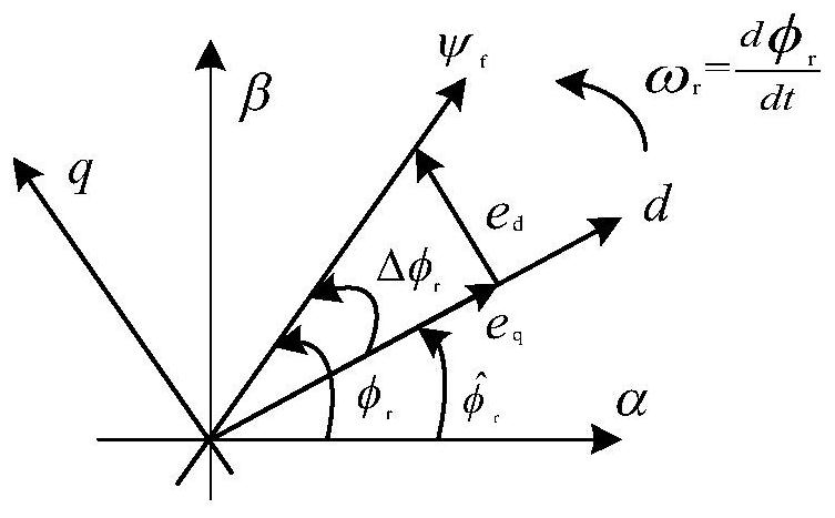
[0034] The permanent magnet synchronous wind turbine is connected to the machine-side full-power back-to-back converter, and connected to the grid through the DC bus and the grid-side converter. The machine-side converter is used to realize the maximum power tracking (MPPT) of the permanent magnet synchronous wind turbine. . By sampling the voltage u αβ and current i αβ The dq-axis voltage and current are obtained through coordinate transformation, the counter electromotive force is calculated by the sliding mode observer, and the rotational speed is estimated by the IPS-PLL method. by omega r =n p ω m will estimate the rotational speed Converted to actual mechanical speed ω m . Then calculate the reference torque where the constant k p is the maximum wind energy capture coefficient. The control loop consists of adjusting the d-axis and q-axis currents of the PMSG, and the d-axis reference current i d,ref Set to 0, use the reference torque to calculate the q-axis ...


PUM


Abstract

A method for estimating the rotor position of a permanent magnet direct drive wind turbine. This method transforms the mathematical model of the permanent magnet synchronous wind turbine in the synchronous rotating coordinate system, and obtains the counter electromotive force per unit time at a fixed time interval and sampling time, as Prepare for its follow-up discretization; aiming at the characteristics of permanent magnet synchronous wind turbines, this application proposes a position estimation method for permanent magnet wind turbines based on IPS‑PLL, and the proposed IPS‑PLL can increase rotor position estimation Accuracy, faster system response, and replaces the SRF‑PLL PI controller parameter tuning process. This evaluation method is effective, and can reduce the speed error by 1 time, and the position error can be controlled below 0.03rad. And the rotor position estimation remains accurate under multiple wind speeds. The robustness of the control system performance can be enhanced.

Description

technical field [0001] The content of the present invention relates to a method for estimating the rotor position of a permanent magnet direct drive wind power generator, which can realize accurate estimation of the rotor position of the permanent magnet wind power generator. It can be used to improve the maximum wind energy capture of the wind power generation system and realize the precise control of the machine-side converter of the permanent magnet wind power generator. Background technique [0002] In the study of wind power generation, researchers at home and abroad hold a positive attitude towards partial curtailment of wind to maintain the output stability of the wind power generation system. Then the maximum wind energy capture in the wind power generation system has become an important factor that can reduce the curtailed wind volume but still maintain the output stability of the power system; and the precise control of the machine-side converter will bring a relat...

Claims


Application Information

Patent Timeline
Patent Type & Authority Patents(China)
IPC IPC(8): H02P9/00H02P21/18H02P21/26H02P101/15H02P103/20
CPCH02P9/009H02P21/18H02P21/26H02P2101/15H02P2103/20
Inventor 邢作霞王鸿毅项尚赵海川崔家平
Owner SHENYANG POLYTECHNIC UNIV
Learn More