Eureka AIR delivers breakthrough ideas for toughest innovation challenges, trusted by R&D personnel around the world.

Transducer with large-size flange

A technology of flanges and horns, which is applied in the direction of fluid using vibration, can solve the problems of ultrasonic vibration energy loss, machine tool damage, machine tool spindle impact, etc., and achieve the effect of ensuring rigidity

Pending Publication Date: 2019-02-19
CONPROFE TECH GRP CO LTD +1
View PDF9 Cites 0 Cited by
  • Summary
  • Abstract
  • Description
  • Claims
  • Application Information

AI Technical Summary

Problems solved by technology

[0003] In the prior art, the transducer is connected to the ultrasonic processing device through a flange. When the transducer is connected to the ultrasonic processing device body in the ultrasonic processing device, a large part of the ultrasonic vibration will be transmitted to the ultrasonic device body, resulting in ultrasonic vibration The loss of energy, the efficiency of ultrasonic machining is low, this is because: on the one hand, the existing transducer does not have a vibration-damping structure, on the other hand, the flange size of the existing transducer is relatively small, and the flange of the small size More ultrasonic vibrations will be transmitted to the body of the ultrasonic device; in addition, when the transducer is applied to the ultrasonic handle, the transducer is connected to the handle body, and part of the ultrasonic vibration is connected to the rear end of the handle through the handle body. The transmission of the machine tool spindle will not only affect the rotation of the machine tool spindle, but also cause impact on the machine tool spindle and even cause damage to the machine tool

Method used


Image

  • Transducer with large-size flange
  • Transducer with large-size flange
  • Transducer with large-size flange

Examples


Embodiment 1

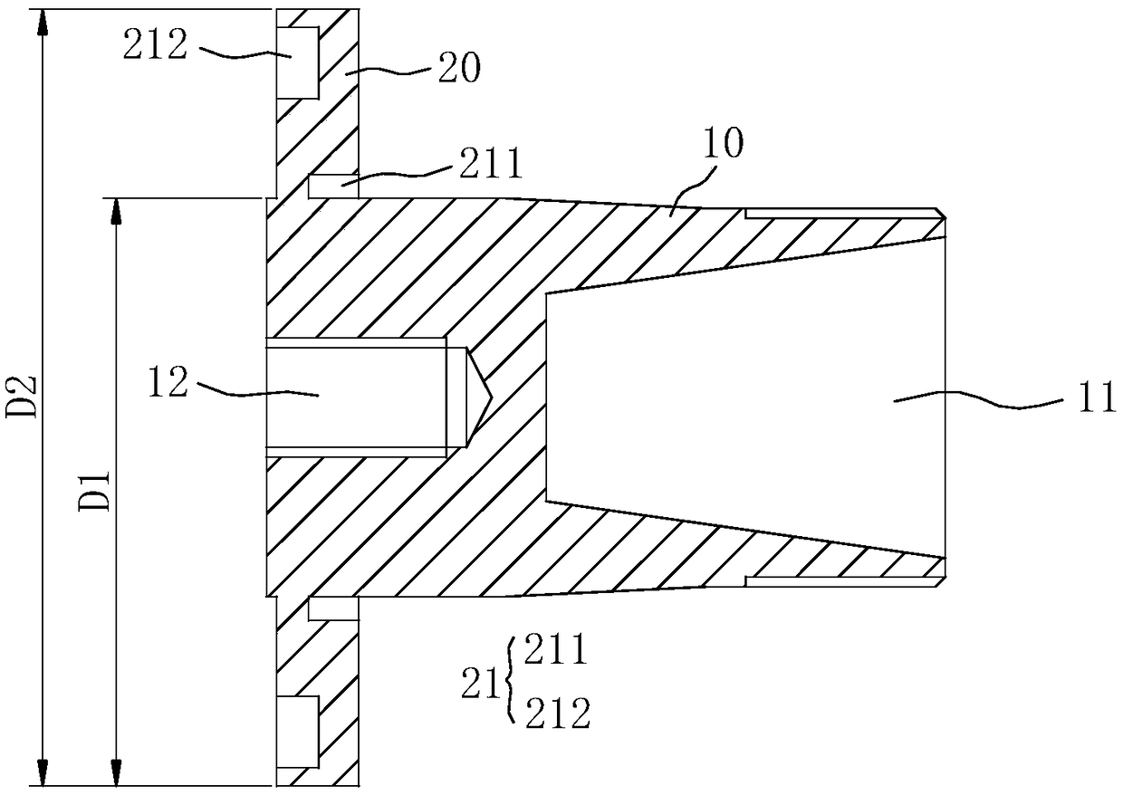
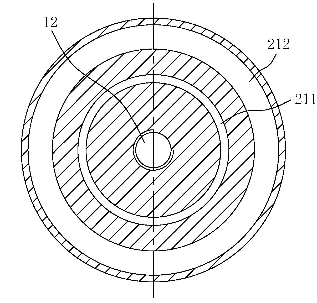
[0034] Such as figure 1 and figure 2 As shown, the horn in this embodiment includes a horn body 10 and a flange 20 integrally formed on the outer periphery of the horn body 10, and the front end of the horn body 10 is used for installing processing tools, so The outer periphery of the flange 20 is used to connect with the body of the ultrasonic processing device; in order to reduce the loss of ultrasonic vibration energy, a vibration-damping structure 21 is provided on the flange 20, and the vibration-damping structure 21 can reduce the ultrasonic vibration from the variable The rod body 10 transmits to the body of the ultrasonic processing device to ensure that the ultrasonic vibration energy is effectively transmitted to the processing tool, and then to the processed material through the processing tool, so as to improve the ultrasonic processing efficiency of the processing tool.

[0035] Taking the ultrasonic tool holder as an example, when the ultrasonic tool holder ado...

Embodiment 2

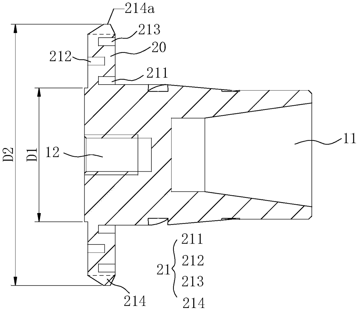
[0045] Please refer to the attached image 3 and Figure 4 As shown, the difference between the horn in this embodiment and the first embodiment is that, in addition to the first annular groove 211 and the second annular groove 212, the damping structure 21 also includes a The third annular groove 213 on the front face is formed with the center of the front end face of the flange 20 as the center, and the diameter of the third annular groove 213 is larger than the diameter of the second annular groove 212 .

[0046] Exemplarily, in this embodiment, the outer diameter of the horn body 10 is 20 mm, the outer diameter of the flange 20 is 39 mm, and the larger flange 20 can ensure the overall rigidity of the horn, and compared to As for the first embodiment, by providing more grooves on the flange 20 , it is possible to further reduce the transmission of ultrasonic vibrations to the body of the ultrasonic processing device through the flange.

[0047] Please continue to see atta...


PUM

PropertyMeasurementUnit
Outer diameteraaaaaaaaaa
Lengthaaaaaaaaaa

Abstract

The invention relates to the technical field of ultrasonic machining, and discloses a transducer with a large-size flange and an amplitude changing pole of the transducer. The amplitude changing polecomprises an amplitude changing pole body and the flange arranged on the outer edge of the amplitude changing pole body. The front end of the amplitude changing pole body is used for installing a machining tool, and the periphery of the flange is used for being connected with an ultrasonic machining device body. The flange is provided with a damping structure for reducing transmission of ultrasonic vibration from the amplitude changing pole body to the ultrasonic machining device body. The range of the specific value of the outer diameter of the flange to the outer diameter of the amplitude changing pole body is 1.5:1-3:1. The transducer with the large-size flange and the amplitude changing pole of the transducer have the beneficial effects that through increasing of the radial size of theflange, integral rigidity of the amplitude changing pole can be ensured, meanwhile, the damping structure can be better arranged on the flange, ultrasonic vibration transmitted to the ultrasonic machining device body from the amplitude changing pole through the flange can be effectively reduced, accordingly, ultrasonic vibration energy losses are reduced, it is ensured that the ultrasonic vibration energy is effectively transmitted to the machining tool, and accordingly the ultrasonic machining efficiency of the machining tool is improved.

Description

technical field [0001] The invention relates to the technical field of ultrasonic processing, in particular to a transducer with a large-size flange and a horn thereof. Background technique [0002] The transducer is the key mechanism that provides ultrasonic vibration energy in the ultrasonic processing device. Its working principle is to use the piezoelectric effect or magnetostrictive effect to convert the frequency electrical signal into high-frequency ultrasonic vibration, and transmit the ultrasonic vibration energy to the processing tool. To process the workpiece. Among them, the processing tools can be cutting tools, grinding heads, etc., and the transducers are mainly used in ultrasonic processing devices such as ultrasonic tool handles, ultrasonic fixtures, ultrasonic spindles, and ultrasonic machine tools. [0003] In the prior art, the transducer is connected to the ultrasonic processing device through a flange. When the transducer is connected to the ultrasonic...

Claims


Application Information

Patent Timeline
IPC IPC(8): B06B1/06
CPCB06B1/06B06B2201/55
Inventor 李伟秋颜炳姜
Owner CONPROFE TECH GRP CO LTD
Why Eureka
Eureka Blog
Learn More