Supercharge Your Innovation With Domain-Expert AI Agents!

Method and system for controlling corner deformation of laser welding T-joint

A laser welding and deformation control technology, applied in laser welding equipment, welding equipment, manufacturing tools, etc., can solve the problems of high cost of tooling, angular deformation of T-joints, complicated process, etc., and achieve the effect of reducing welding heat input

Active Publication Date: 2021-02-02
AVIC BEIJING AERONAUTICAL MFG TECH RES INST
View PDF5 Cites 0 Cited by
  • Summary
  • Abstract
  • Description
  • Claims
  • Application Information

AI Technical Summary

Problems solved by technology

However, due to the hysteresis effect of welding deformation, there will still be angular deformation of the T-joint after the tooling is removed. In addition, because the tooling mold has a compression or adsorption function, the structure is complicated and the tooling cost is high
Another method to control the angular deformation of T-joints is post-welding orthopedics: for aluminum alloy parts, shot peening, aging, overall heat treatment and other methods are often used, the process is relatively complicated, the cost is high, and the orthopedic effect is not obvious

Method used


Image

  • Method and system for controlling corner deformation of laser welding T-joint
  • Method and system for controlling corner deformation of laser welding T-joint
  • Method and system for controlling corner deformation of laser welding T-joint

Examples


Embodiment 1

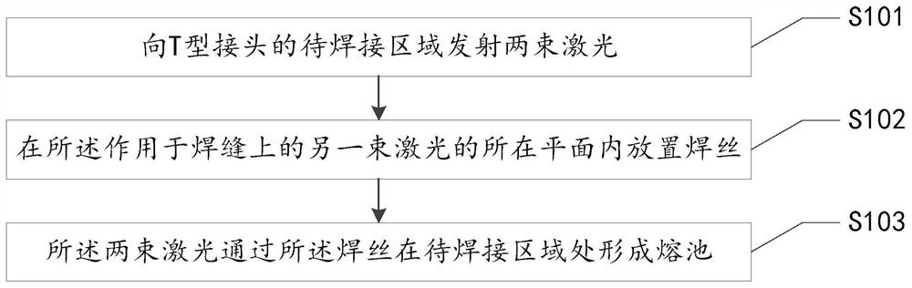
[0033] Such as figure 1 As shown, this embodiment proposes a method for controlling the angular deformation of a laser welded T-joint, the method comprising:

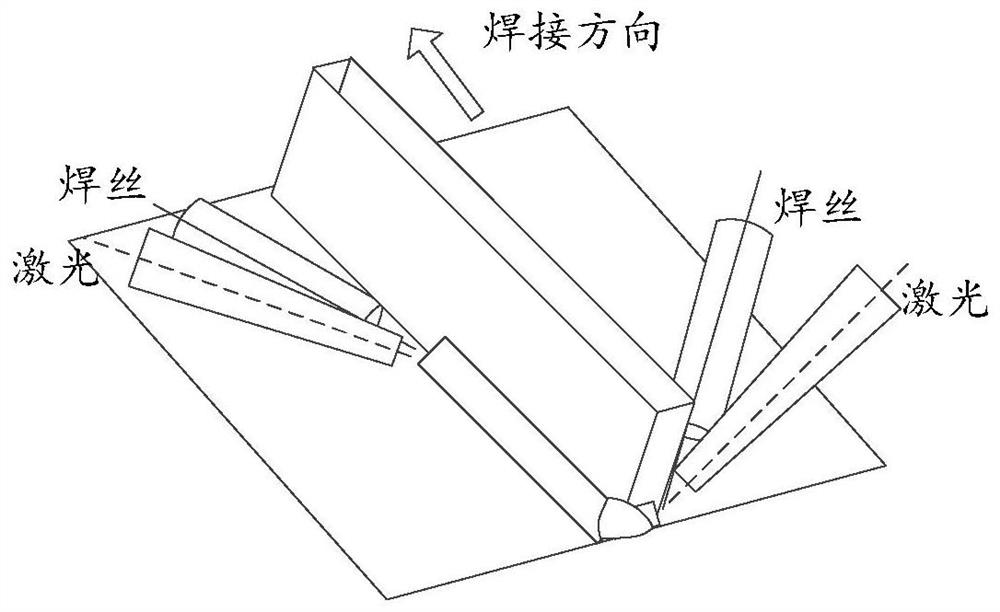
[0034] S101. Emit two laser beams to the area to be welded of the T-shaped joint, the two laser beams are located on the same side of the T-shaped joint; wherein, one of the two laser beams acts on the tendons of the T-shaped joint On the strip, another beam of laser acts on the weld between the rib and the bottom plate of the T-joint;

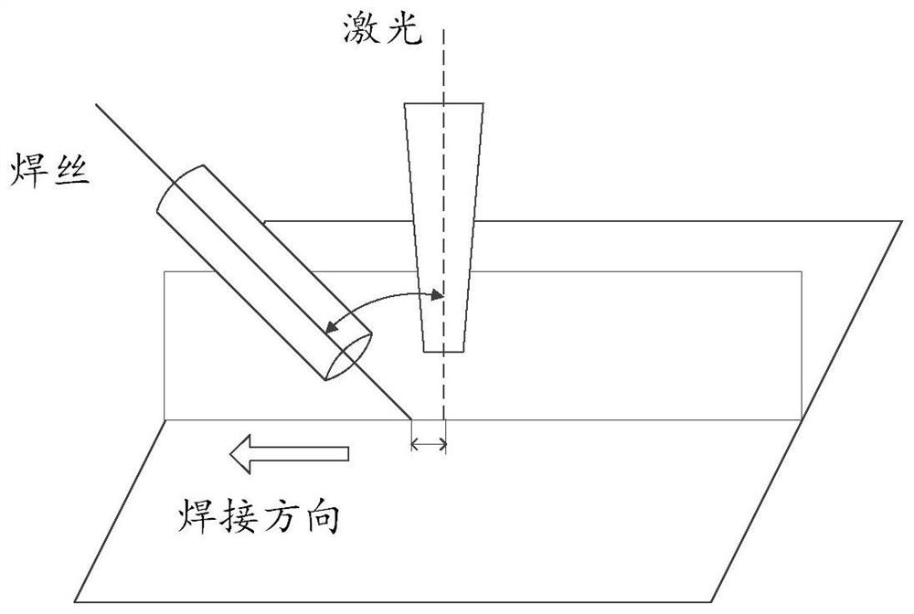
[0035] S102. Place the welding wire in the plane where the other laser beam acting on the weld seam is located;

[0036] S103. The two laser beams pass through the welding wire to form a molten pool at the area to be welded.

[0037] Specifically, in this embodiment, a high-power Nd.YAG or fiber laser is firstly used as a laser emission source, and the laser light emitted by the laser is split to generate two laser beams through a dual-beam spot welding joint with a splitting function...

Embodiment 2

[0041] Such as Figure 9 As shown, this embodiment proposes a laser welding T-joint angular deformation control system, the system includes a laser and a welding head;

[0042] The laser is used to generate laser light and send the laser light to the welding head;

[0043] The welding head is used to split the laser light sent by the laser into two laser beams, and emit the two laser beams to the area to be welded of the T-shaped joint, so that the two laser beams pass through the welding wire in the area to be welded A molten pool is formed.

[0044]Specifically, in this embodiment, a high-power Nd.YAG or fiber laser is firstly used as a laser emission source, and the laser light emitted by the laser is split to generate two laser beams through a dual-beam spot welding joint with a splitting function. There are two laser beams on both sides of the T-joint rib, which can be welded simultaneously or sequentially. The two laser beams act on the area to be welded respectively ...


PUM


Abstract

The present invention proposes a method for controlling the angular deformation of laser welding T-joints, the method comprising: emitting two laser beams to the region to be welded of the T-joint, and the two laser beams are located on the same side of the T-joint; wherein , one of the laser beams in the two laser beams acts on the ribs of the T-joint, and the other laser beam acts on the weld between the ribs of the T-joint and the bottom plate; The welding wire is placed in the plane of the other laser beam on the laser beam; the two laser beams pass through the welding wire to form a molten pool at the area to be welded. The invention also proposes a laser welding T-shaped joint angular deformation control system. The invention ensures that under the premise that the T-joint ribs are fully penetrated, the welding heat input of the T-joint bottom plate in the laser welding process is reduced, thereby regulating the angular deformation of the T-joint bottom plate caused by shrinkage.

Description

technical field [0001] The present application relates to the field of laser manufacturing, in particular to a method and system for controlling angular deformation of T-joints in laser welding. Background technique [0002] Aluminum alloys and titanium alloys are widely used in aviation, aerospace and other fields because of their high specific strength, high specific stiffness and good weldability. With the increasing demand for the application of new lightweight alloys in weaponry structures, how to improve material utilization and reduce manufacturing costs has attracted widespread attention. Laser welding has the characteristics of high energy density, small heat input, large single-pass penetration, high welding speed, non-contact and no vacuum, etc. Compared with conventional fusion welding methods, the deformation is smaller, which is conducive to the compact design of product structure, structural weight and production cost. It is especially suitable for the manufa...

Claims


Application Information

Patent Timeline
Patent Type & Authority Patents(China)
IPC IPC(8): B23K26/211B23K26/70
CPCB23K26/211B23K26/702
Inventor 何恩光陈俐杨璟王彬赵晓龙
Owner AVIC BEIJING AERONAUTICAL MFG TECH RES INST
Features
  • R&D
  • Intellectual Property
  • Life Sciences
  • Materials
  • Tech Scout
  • Unparalleled Data Quality
  • Higher Quality Content
  • 60% Fewer Hallucinations
Learn More