
Crane beam manufacturing method

A manufacturing method and technology for driving beams, which are applied in the directions of manufacturing tools, auxiliary devices, auxiliary welding equipment, etc., can solve the problems such as the inability to use the production process of driving beams, and achieve clear production operations, scientific methods, and avoid the risk of missed inspections. Effect

Active Publication Date: 2019-02-19
江苏丰华建筑系统集成有限公司
View PDF7 Cites 1 Cited by
  • Summary
  • Abstract
  • Description
  • Claims
  • Application Information

AI Technical Summary

Problems solved by technology

Its disadvantage is that this method can only be used in the straightening process of the stiffened plate, and cannot be used in the production process of the entire driving beam

Method used


Image

  • Crane beam manufacturing method
  • Crane beam manufacturing method
  • Crane beam manufacturing method

Examples


Embodiment Construction

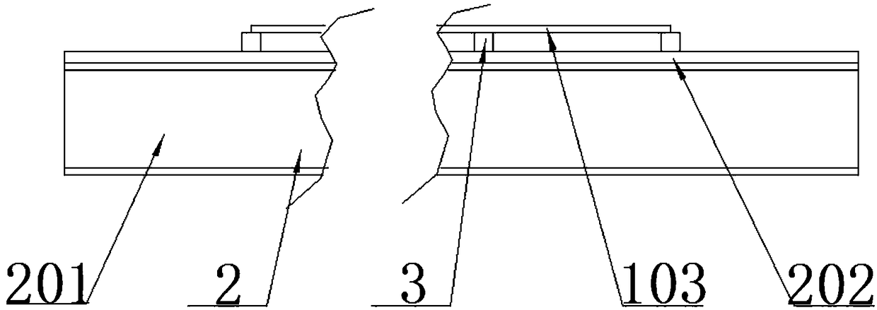
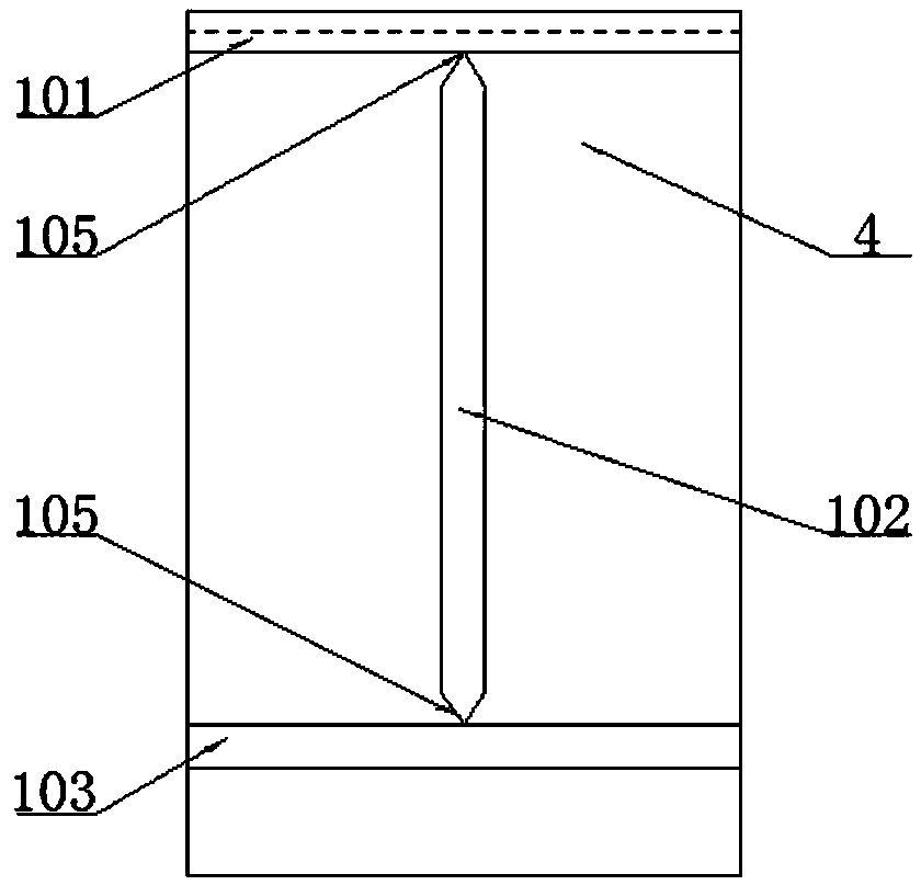
[0020] Such as Figure 1-4 Described, is a kind of manufacturing method of driving beam, comprises the following steps:

[0021] Step 1: Screening of raw materials, selecting long slabs with a thickness of 15-25 mm for the production of the upper flange 101, web 102 and lower flange 103 of the H-shaped steel beam 1, ensuring the flatness error of each long slab Within ±2mm;

[0022] Step 2: Manufacture the tire frame 2. Lay multiple I-beams 201 in the same direction at equal intervals and fix them on the ground. The lower plate of the I-beam 201 is in contact with the ground, and the upper plate is suspended in the air and set horizontally. The levelness of multiple points on the upper plate of the steel 201 ensures that each I-beam 201 is set horizontally, and then hoists a flat plate with a thickness of 20-30mm on each I-beam 201 to form a sealing plate 202 to ensure that each sealing plate 202 The gap between the lower surface and the upper surface of each I-beam 201 is w...


PUM

PropertyMeasurementUnit
thicknessaaaaaaaaaa

Abstract

The invention relates to a crane beam manufacturing method. The method comprises the steps of: (1) screening of raw materials; (2) manufacturing of a bed jig; (3) leveling of cushion blocks; (4) manufacturing of a T-shaped beam; (5) manufacturing of a semi-finished H-shaped steel beam; (6) manufacturing a finished H-shaped steel beam; and (7) manufacturing of a crane beam. The method is scientificand precise, and is clear and logic in production operation; and multiple detecting methods are applied in the checking process for cooperation, and are performed in sequence to prevent the detectionmissing risk so as to guarantee high precision of the produced crane beam.

Description

technical field [0001] The invention relates to the technical field of driving beam manufacturing, in particular to a manufacturing method of a driving beam. Background technique [0002] The existing Chinese patent database discloses a patent titled a method of straightening a driving beam stiffener. The patent application number is 201510222730.0, the application date is 20150505, the application publication number is CN106180266A, and the application publication date is 20161207. The method Including the following steps: a. Making the straightening device, the straightening device includes a base, a bracket, a straightening bottom plate, a support block, and a straightening top plate, wherein the base is H-shaped steel, the bracket is a rectangular tube, the bracket and the base are vertically welded, and the bracket The other end of the straightening bottom plate is solidly welded with the straightening bottom plate. The straightening bottom plate is a 20mm thick rectang...

Claims


Application Information

Patent Timeline
Patent Type & Authority Applications(China)
IPC IPC(8): B23P15/00B23K37/00B23K101/28
CPCB23K37/00B23P15/00
Inventor 颜笑董青裴巧琴
Owner 江苏丰华建筑系统集成有限公司
Learn More